FREE 1 to 3-Day Delivery on Orders $119+ Details
How to Install an Edelbrock Victor Jr. Carbureted Intake Manifold on Your 1999-2004 Mustang GT
Installation
PLEASE study these instructions carefully before beginning this installation. Most installations can be accomplished with common tools and procedures. However, you should be familiar with and comfortable working on your vehicle. If you do not feel comfortable performing this installation, it is recommended to have the installation completed by a qualified mechanic. If you have any questions, please call our Technical Hotline at: 1-800-416-8628, 7:00 am - 5:00 pm, Pacific Standard Time, Monday through Friday or e-mail us at [email protected].
IMPORTANT NOTE: Proper installation is the responsibility of the installer. Improper installation will void your warranty and may result in poor performance and engine or vehicle damage.
DESCRIPTION: This intake manifold is designed to allow the use of a carburetor on a Ford 4.6L Modular Single Overhead Cam engine. This will eliminate the use of the OEM fuel injection system and is intended for longblocks that have been installed in early model or custom vehicles. It is also intended for use in racing classes where fuel injection is not allowed or is not desirable. The #2839 includes an electronic Timing Control Module, which picks up MAP, Crank Position, and Cam Position, and drives the stock Coil-on-Plug system. The Timing Control Module comes loaded with a basic timing curve and rev limit, both of which can be easily modified using a laptop and the included Pro-Data software. The #2838 does not include the electronics, but they may be purchased seperately as part #91237.
KIT CONTENTS (2838 & 2839):
- 1 Victor Jr. Intake Manifold
- 1 Fitting; 3/8 NPT to 3/4” hose
- 2 Plugs; 3/8 NPT
- 8 Bolt; M6 x 1.0 x 30mm hex flange head
2839 Only:
- 1 Edelbrock/MSD Timing Control Module
- 1 2-Bar Manifold Absolute Pressure (MAP) Sensor
- 1 MAP Sensor Mounting Bracket
- 1 9-Pin Serial Cable
- 1 Wiring Harness
- 1 Pro-Data Software Installation CD
- 1/8 NPT to 1/4” Hose Adapter Fitting
- 1 Mounting Hardware Kit Including:
- 4 Sheet Metal Screws
- 4 Mounting Grommets
- 4 Mounting Spacers
- 2 5mm x .8 x 30mm Torx Button Head Screws
- 2 5mm Lock Nuts
2 1/4” rubber hose; 9” long
- 2 3/16” Flat Washers
- 2 5/16”-18 x 1/2” Hex Cap Bolt
- 2 5/16” Flat Washers
INSTALLATION PROCEDURE
NOTE: This intake manifold is not designed for use in vehicles equipped with the 4.6L engine from the factory. It is only intended to be used on engines that have been swapped into a custom application where modifications can be made as necessary. These installation instructions do not attempt to cover the steps necessary to convert a fuel injected vehicle to carburetion, they only cover what is needed to install this intake and the related electronics on a properly prepared longblock.
MANIFOLD INSTALLATION:
1. Use only the recommended OEM intake gaskets with this manifold.
2. Fully clean the intake manifold and cylinder head flanges, as well as the end seal surfaces of the engine block. No sealants or adhesives are necessary.
3. Install the manifold on the block. Lightly coat the manifold bolts with 30W motor oil then gently thread them into the heads to hold the intake in place. Do not apply any torque to the bolts at this time.
4. Install the themostat and allow it to drop into the machined recess.
The o-ring supplied with the thermostat should then be pressed in and compressed by the thermostat housing.
5. The manifold bolts (including the thermostat housing bolts) can now be tightened according to the torque sequence (See Figure 1).
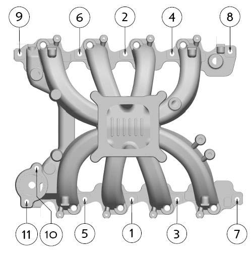
Figure 1 - Torque Sequence Torque manifold bolts to 15-20 ft/lbs.
MAP SENSOR INSTALLATION:
1. Apply a bit of liquid Teflon thread sealant to the threads of the supplied 1/8” NPT to 1/4” hose fitting and install the fitting into the 1/8” NPT hole in the intake manifold plenum (See Figure 2).
2. Attach the MAP sensor to the supplied bracket (See Figure 3).
3. Install the sensor/bracket assembly on the intake manifold using the throttle cable bracket bolt hole bosses (See Figure 4). If using a Ford throttle cable bracket, install the sensor assembly on top of the bracket.
4. Connect the sensor to the fitting with the supplied hose.
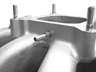
Figure 2 - Map Sensor Fitting
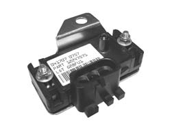
Figure 3 - Sensor/Bracket Assembly
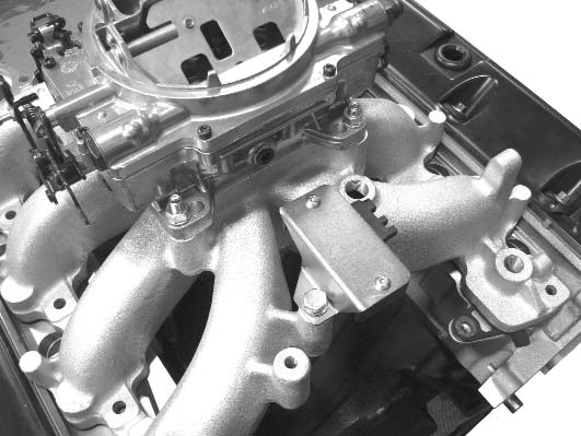
Figure 4 - Assembly Mounting
TIMING CONTROL MODULE INSTALLATION:
1. Using the hardware supplied with the Timing Control Module, mount the unit in a suitable location inside the engine compartment, such as the firewall, or inner fender. Mount the module so that the main harness can be easily connected. Bear in mind that the shorter side of the coil pack wires will be routed to the passenger side bank.
2. Route the harness from the control module to the passenger side of the engine, towards the front. Locate the Crankshaft Position Sensor connector. It is a two wire connector with red and black wires at the end of a long section of harness which is encased in a smooth, rubberized, dark grey heatshield. Route this line down the passenger side of the engine, and connect it to the Crankshaft Position Sensor. The Crankshaft Position Sensor is located on the front of the passenger side of the engine, just above the oil pan rail.
3. Locate the MAP Sensor connector. It is the three wire connector with orange, green, and brown wires. Connect this to the MAP Sensor on the rear of the manifold.
4. Locate the Camshaft Position Sensor connector. It is a two wire connector with tan and brown wires extending from a length of rubberized heatshield. Route this wire along the driver side of the intake manifold and down the front of the block. Connect the wire to the Camshaft Position Sensor, located at the front driver side of the block, just below the valve cover rail.
5. Attach the wire connectors to the coil pack associated with the attached cylinder number. The shorter coil wire set will be routed to the passenger side bank, while the longer wire set will be routed along the driver side bank. The connector on the end of the harness will go to the cylinder closest to the front of the engine and the rest of the connectors should line up with their respective coils.
6. Locate the portion of the harness with the gray, four wire connector extending from the coil pack wire set. The ring tab is a ground and should be mounted to an unpainted area of the block or frame. The two wire plug that also extends from the gray connector will be cut off, and the red wire should be routed to a switched (only has power when the key is on) 12 volt power source. The yellow and brown wire will not be used and should be taped off to prevent a short.
7. The loose yellow wire that extends directly out of the main harness plug is the tachometer lead. This wire should be taped off and secured if you are not using a tach. The pink and blue wires will attach to a two-step timing retard box if you are using one, otherwise they should be taped off and secured, as well.
CARBURETOR RECOMMENDATIONS: Manifold will accept any standard square bore flange carburetor, including all Edelbrock Thunder AVS and Performer models. Due to engine efficiency and runner design, we recommend the use of a 600 cfm or larger carburetor. Dyno testing was conducted with our 750 cfm high performance carburetor (part #1407). The best results were achieved with the stock primary jet, .075” x .047” metering rods (part #1459), and .100” secondary jets (part #1428). We recommend using the stock calibration to establish a baseline, and tuning accordingly from there. A smaller carburetor, such as the Thunder AVS 650 cfm (part #1806), would be preferable for street use particularly if the stock camshaft will be reused.
CAMSHAFT AND HEADERS: Edelbrock does not currently make a camshaft for this engine. Although the stock cam can be used, we recommend a more aggressive grind that will take full advantage of the improved runner design and flow capacity. Headers are not strictly necessary, but their use is strongly recommend. Primary tube diameter should be no less than 1-5/8” with a 3” collector.
THROTTLE AND ACCESSORY BRACKETS: Throttle and kickdown brackets on some vehicles may require modification to fit. A universal throttle cable bracket is also available under the Russell brand name (part #611069).
DISTRIBUTOR: The Ford 4.6L Modular engine uses a direct fire Coil-On-Plug ignition distributorless ignition system. A standalone ignition control module is available seperately (#91237) and is included with the #2839 version of this manifold. Please refer to the seperate instruction sheet for specific installation and tuning recommendations.
Related Guides
-
Installation
-
Installation
-
Installation