FREE 1 to 3-Day Delivery on Orders $119+ Details
Best Sellers


How To Install an Edelbrock Performer RPM II EFI Intake Manifold on Your 1986-1995 5.0L Mustang
Shop Parts in this Guide
Installation
PLEASE study these instructions carefully before beginning this installation. Most installations can be accomplished with common tools and procedures. However, you should be familiar with and comfortable working on your vehicle. If you do not feel comfortable performing this installation, it is recommended to have the installation completed by a qualified mechanic. If you have any questions, please call our Technical Hotline at: 1-800-416-8628, 7:00 am - 5:00 pm, Pacific Standard Time, Monday through Friday or e-mail us at [email protected].
IMPORTANT NOTE: Proper installation is the responsibility of the installer. Improper installation will void your warranty and may result in poor performance and engine or vehicle damage.
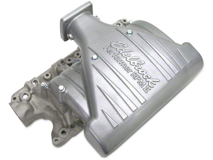
DESCRIPTION: The Performer 5.0 RPM II intake manifold is designed for 1986-1995 5.0L Mustangs and passenger vehicles (will not fit trucks). It is ideally suited to street/strip applications with an RPM range of 1500-6500 RPM. The manifold features a V-shaped crossover with an increasing crosssectional area leading to large, tapered runners. Manifold may not clear factory hood of 1994-1995 Mustang. Use of an aftermarket hood is recommended. Manifold WILL NOT clear factory 1994-1995 Mustang strut tower brace. Use Edelbrock Strut Tower Brace #5225.
KIT CONTENTS:
- 1 Base manifold
- 1 Upper manifold
- 1 Plenum access cover
- 1 Base-to-upper gasket
- 1 Plenum cover gasket
- 1 10” length 5/32” vacuum line
- 1 PCV valve baffle plate
- 2 #12 drive screws
- 4 5/16” -18 x 1-1/4” flange head bolts
- 2 5/16” -18 x 4-3/4” flange head bolts
- 2 5/16”-18 x 6-1/4” flange head bolts
- 8 6mm x 1.0 x 10mm flange head bolts
- 1 5/16” x 1-3/8” carb stud
- 1 5/16”-24 hex nuts
- 1 5/16” split lockwashers
- 1 1/8 pipe to 3/8” hose fitting
- 1 1/8 pipe to 3/16” hose fitting
- 1 3/8 pipe to 3/8” hose fitting
- 1 3/8 pipe 90-degree fitting
- 1 3/16” vacuum tee fitting
- 2 1/8 pipe plugs
- 1 3/8 pipe plugs
Emissions Systems: This manifold is intended as a direct replacement for the factory intake manifold. All emissions related factory components are to be retained and functional. The manifold is, therefore, legal for street use in all 50 states, and no C.A.R.B. E.O. number is required. Check local laws for requirements.
ACCESSORIES & INSTALLATION ITEMS: Major recommendations are listed below. See our catalog for details. To order a catalog, call (800) FUN-TEAM, or visit www.edelbrock.com.
THROTTLE BODY RECOMMENDATIONS:
| APPLICATION | THROTTLE BODY | PARTS REQUIRED FOR INSTALLATION |
|---|---|---|
| 1986-1993 | 3825 (70mm) | 70mm EGR Plate #3828 |
| 3826 (75mm) | 75mm EGR Plate #3829 | |
| 1994-1995 | 3845 (70mm) | Throttle Body Adapter #3835 and Mustang EGR Supply Spacer #8025 |
| 3846 (75mm) | Throttle Body Adapter #3835 and Mustang EGR Supply Spacer #8025 |
NOTES: A 70mm throttle body is recommended for most street/strip applications as a part of our Performer RPM Power Package. 75mm throttle bodies should be used in higher horsepower applications (Port matching required). The air valve (throttle body) location is 0.50” higher than the stock location. If parts required for installation are unavailable locally, contact Edelbrock directly.
CAMSHAFT AND HEADERS: Performer RPM Series manifolds are compatible with aftermarket camshafts and headers designed to work in the 1500- 6500 rpm range. Edelbrock recommends using Ford SVO X-303 or Z-303 camshafts. Edelbrock has developed dyno-matched, street-proven Tubular Exhaust Systems #6845 or #6883 (equal length) and Cat-Back exhaust system #5645 or #5646, which are suitable for use with the RPM II manifold on 1986 through 1993 Mustangs. Consult your dealer, Edelbrock catalog, or Edelbrock Technical Hotline for applications.
CYLINDER HEADS: Manifold must be used with modified or high performance cylinder heads to achieve full power potential. Edelbrock Performer 5.0L or Performer RPM cylinder heads are fully assembled, ready to run cylinder heads that are designed to work with this intake manifold.
GASKETS: Do not use competition-style intake gaskets for this street manifold. Due to material deterioration over time, internal leakage of vacuum, oil, and coolant may occur. Replacement access cover and manifold top to manifold bottom gaskets available as Edelbrock #7233. OEM Ford gaskets will not fit.
PREP AND TUNING FOR POWER:
NOTE: Local emission laws must be checked for legality of any tuning or ignition changes.
- Aftermarket ignition kits may be used with Performer RPM series manifolds.
- Use modified or high performance cylinder heads such as our Performer RPM, and port-match the manifold to the heads.
- The compression ratio should be at least 9.5 to 1 to work properly with camshafts that operate in the 1500-6500 RPM range.
- Installation of aftermarket headers, camshafts or both with an Edelbrock Performer RPM series manifold may require additional tuning.
| INTAKE MANIFOLD | REFERENCE | RECOMMENDED GASKET |
|---|---|---|
| 7123, 71233 | (None) | Edelbrock #7220 Port: 1.20” x 2.00”, .060” Thickness |
NOTE: To ensure maximum performance and a proper seal, Edelbrock gaskets which are specifically designed and manufactured for use with Edelbrock parts must be used.
INSTALLATION PROCEDURE
Before Beginning: This installation can be accomplished using common tools and procedures. However, you should have a basic knowledge of automotive repair and modification and be familiar with and comfortable working on your vehicle. If you do not feel comfortable working on your vehicle, it is recommended to have the installation completed by a qualified mechanic. Keeping a service manual for your specific vehicle on hand for reference is helpful.
REMEMBER: WHEN WORKING AROUND GASOLINE, DO NOT SMOKE, and KEEP ALL OPEN FLAMES, SPARKS AND OTHER SOURCES OF IGNITION AWAY FROM THE WORK AREA. Failure to do so can result in a FIRE or EXPLOSION.
REMOVAL:
1. Disconnect battery negative cable and drain cooling system.
2. Disconnect necessary electrical connections, control cables, linkages, vacuum hoses, ventilation hoses, and coolant hoses at throttle body and manifold. Do not disconnect fuel lines unless absolutely necessary. Special tools and procedures are required to re-install fuel lines. See “FUEL LINE REMOVAL AND INSTALLATION”.
3. Remove distributor cap and spark plug wires as an assembly. Place reference mark on distributor for rotor alignment during reassembly. Remove retaining bolt and distributor.
4. Remove cover plates, retaining bolts, upper intake manifold and gasket.
5. Remove accessory brackets attached to lower manifold. Remove heater tube assembly from lower manifold. Remove retaining bolts, lower manifold, gaskets, and seals.
BAFFLE INSTALLATION
IMPORTANT: PCV valve baffle must be installed before manifold is bolted to engine!
1. Install PCV valve baffle on bottom of manifold using two-drive pins supplied. Hammer pin in the round hole first, then install other pin in the oval hole.
INSTALLATION
1. Clean all gasket surfaces. Apply Edelbrock Gasgacinch sealant, #9300 to the cylinder head side of the gasket as well as head surfaces. Allow to air-dry.
2. Install intake manifold gaskets on head.
3. Eliminate the end seals. Use RTV silicone sealer instead (O2 Sensor Safe). Apply a bead of sealant approximately 1/4” high across the front and rear block end seal surfaces, overlapping the intake gasket at the four corners. This method eliminates end seal slippage and deterioration.
4. For ease of installation, we recommend using Edelbrock manifold bolt and washer kit #8524. It may be necessary to re-use the original stud bolt to hold heater tube bracket in hole #3 (See Figure 1).
5. Install lower intake manifold and retaining bolts. Tighten bolts to 15- 18 ft./lbs. in sequence (See Figure 1).
6. If fuel rail and injectors were disconnected, install components with new O-rings on fuel lines. Use only specified fuel resistant brown O-rings. Lightly coat O-rings with clean O-ring lube (brake lube) before installing. Clean fittings and replace garter spring, if necessary.

Figure 1 - Intake Manifold Tightening Sequence, Manifold Top-To-Bottom Fastener Locations, and Firing Order Torque Bolts to 18-20 Ft./Lbs. 5.0L Ford Firing Order 1-3-7-2-6-5-4-8 Turn Distributor Clockwise to Advance Timing
7. Apply a thin film of O2 sensor safe silicone to the plenum access cover flange on the intake manifold. Carefully place the gasket onto the flange, apply a thin film of silicone to the gasket, and carefully set the cover plate onto the gasket. Apply thread locker to the eight cover bolts and snug them down, starting at the center and working your way out. DO NOT OVERTIGHTEN. The bolts only need to be snug.
8. Install upper manifold and gasket (dry) using hardware supplied (See Figure 1 and Fastener Location Chart Below). Upper manifold must be positioned so that the throttle body is on the passenger side of vehicle, not driver’s side. Do not overtighten manifold base-to-manifold upper fasteners. Use a short box or open end wrench only.
| LOCATION | FASTENER |
|---|---|
| A | 5/16-18 x 1-1/4” Bolt |
| B | 1-3/8” Stud |
| C | 5/16-18 x 6-1/4” Bolt |
| D | 5/16-18 x 4-3/4” Bolt |
Fastener Location Chart
9. To smooth the crossover, we have eliminated the stock vacuum tree. Use the 3/8” NPT 90-degree elbow and 3/8” NPT to 3/16” hose fitting in the rear facing 1/8” NPT boss on the crossover (next to the EGR plate). Use the vacuum line supplied and “tee” to feed the fuel pressure regulator and the MAP sensor from this source.
10. Remove original throttle valve/EGR plate studs from stock manifold and install in new manifold. To re-install remaining components, reverse removal procedure. Adjust all control cables. If automatic transmission equipped using Edelbrock throttle body, refer to throttle body instructions for transmission T.V. (throttle valve) cable linkage adjustment. Fill cooling system with coolant. Connect battery negative cable.
11. A re-torque of the manifold bolts is recommended after several operation cycles (start-up, bring to operating temperature, cooldown). Re-torque when engine is cold.
FUEL LINE REMOVAL AND INSTALLATION
CAUTION: Do not remove fuel lines unless necessary.
CAUTION: Fuel system is under pressure. Pressure must be released before servicing fuel system components.
1. Remove fuel cap to release fuel tank pressure. Using EFI pressure gauge (T80L-9974-B), release fuel pressure from fuel pressure relief on fuel rail.
2. Before disconnecting fuel lines, disconnect negative battery cable. To disconnect fuel lines, remove retaining clip from outside of fuel line coupling.
3. Use Spring Lock Coupling Remover (D87L-9280-A) for 3/8” line or (9D87L-9280-B) for 1/2” line. Install spring lock coupling remover on fuel line so it enters cage opening (See Figure 2).
4. Push spring lock coupling remover into cage opening to release female fitting from garter spring. Pull couplings apart. Remove spring lock coupling remover.
5. To install fuel lines, install new O-rings on fuel lines. Use only specified fuel resistant brown O-rings. Before installing, lightly coat O-rings with clean O-ring lube (brake lube). Clean fittings and replace garter spring, if necessary.
6. Fit female fitting to male fitting and push until garter spring snaps over flared end of female fitting. Ensure lines are locked together and garter spring is over female fitting flared end.
7. Install retaining clip. Ensure horseshoe portion of clip is over coupling. Do not install retaining clip over rubber fuel line.
NOTE: Black retaining clip should be installed on fuel supply line and Gray clip on fuel return line.
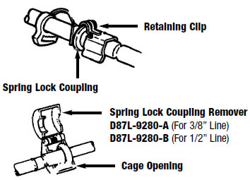
Figure 2 - Disconnecting Fuel Lines
Best Sellers
Related Guides
-
Installation
-
Installation
-
Installation