Best Sellers
How To Install a Roush Quad Tip Active Axle-Back Exhaust on your 2015-2016 Mustang GT
Installation Time
5 hours
Tools Required
- Trim Tool
- Tape Measure
- Scissors
- Masking Tape
- Center Punch
- Drill
- 1/4" Drill Bit
- Philips Head Screwdriver
- Wire Cutters
- 7 mm Deep Socket
- 8 mm Socket
- 10 mm socket
- 13 mm socket
- 15 mm socket
- Torque Wrench
- Small Pick
- Flat-head screwdriver
- Razor Blade
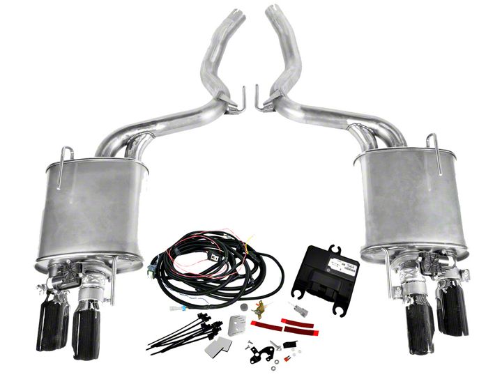
Shop Parts in this Guide
ROUSH Active Exhaust Installation Instructions
P/N: 421926 (R1315-5231AV)
Fastback GT V8 – Convertible GT V8
Fastback EcoBoost I4 – Convertible EcoBoost I4
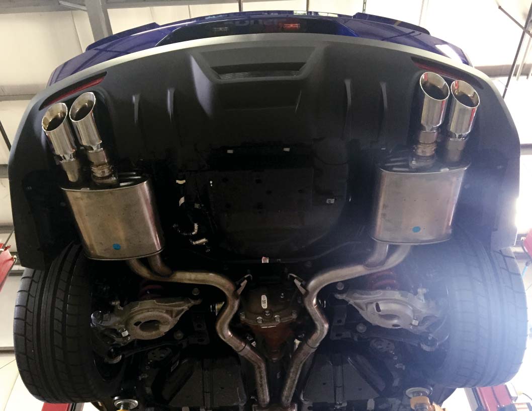
*Vehicle Shown with ROUSH Rear Valance and Quad Tip Exhaust. Application: 2015 Ford Mustang
Important Note:
Before installing the ROUSH Performance Product, please read through the installation procedure and verify that all items are present. If you are missing hardware or have any questions, please contact ROUSH Performance at 1-800-59-ROUSH, 9:00 AM to 5:00 PM EST.
PACKING LIST FOR ROUSH ACTIVE EXHAUST
If you are missing any items, please call us toll free at 1-800-59-ROUSH.
Description | Part Number | Quantity |
Active Exhaust Upgrade Kit | R1315-5231AV | |
Exhaust Pipe with Valve – LH | 1315-6506LH | 1 |
Exhaust Pipe with Valve – RH | 1315-6505RH | 1 |
Flashed Controller, Active Exhaust | 1315-5E260 | 1 |
Vehicle Ready Wiring Harness | 1315-9L430 | 1 |
OBDII Active Exhaust Programmer | 1315-14489 | 1 |
Hardware Kit – Active Exhaust | 1315-5231AVHK | 1 |
Switch, Mode Selector | 1315-13K724 | 1 |
Switch Plate, Metal with Engraving | 1315-11806 | 1 |
Switch Bracket | 1315-7Z374 | 1 |
Bolt – M4 x 0.7 x 10 | 90116A207 | 2 |
Push Nut – 3/16” | 94807A026 | 2 |
Washer – M4 Nylon | 91755A215 | 3 |
Zip Tie with Edge Clip | 156-00865 | 7 |
Knob, Knurled Style | 1315-AVKNOB | 1 |
Set Screw – M3 x 0.5 x 6 | 93245A100 | 1 |
J-Clip – M6 | 95210A175 | 1 |
Bolt – M6 x 31 HEX | R18020009-00 | 1 |
Foam Tape 30 mm x 35 mm x 7.9 mm | 1315-5E260TP | 2 |
Micro Fuse – 10 AMP | APT-10A | 1 |
Zip Tie – 7” | CTUV740 | 20 |
Multipurpose O-Ring, 5.6 mm | 9262K215 | 1 |
LIMIT OF LIABILITY STATEMENT
The information contained in this publication was accurate and in effect at the time the publication was approved for printing and is subject to change without notice or liability. ROUSH Performance Products (RPP) reserves the right to revise the information presented herein or to discontinue the production of parts described at any time.
SAFETY PRECAUTIONS
CAREFULLY READ THE IMPORTANT SAFETY PRECAUTIONS and WARNINGS BEFORE PROCEEDING WITH THE INSTALLATION!
Appropriate disassembly, assembly methods and procedures are essential to ensure the personal safety of the individual performing the kit installation. Improper installation due to the failure to correctly follow these instructions could cause personal injury or death. Read each step of the installation manual carefully before starting the installation.
Always wear safety glasses for eye protection.
Place ignition switch in the OFF position.
Always apply the parking brake when working on a vehicle.
Block the front and rear tire surface to prevent unexpected vehicle movement.
If working with a lift, always consult vehicle manual for correct lifting speci cations.
Operate the engine only in well-ventilated areas to avoid exposure to carbon monoxide.
Do not smoke or use ammable items near or around the fuel system.
Use chemicals and cleaners in well-ventilated areas.
Batteries produce explosive gases, which can cause personal injury. Therefore, do not allow ames, sparks or ammable substances to come near the battery.
Keeps hands and any other objects away from the radiator fan blades.
Keep yourself and your clothing away from moving parts when the engine is running.
Do not wear loose clothing or jewelry that can get caught in rotating parts or scratch surface nishes.
Allow the engine, cooling system, brakes and exhaust to cool before working on a vehicle.
WORK SAFELY!
Perform this installation on a good clean level surface for maximum safety and with the engine turned off.
ACTIVE EXHAUST INSTALLATION
Refer to the installation manual titled “ROUSH Quad Tip Exhaust” under part numbers 421920, 421921, 421922 and 421923 for installation of the Quad Tip Exhaust System. Refer to the installation manual titled “2015 Mustang Rear Valance” under part numbers 421894 and 421919 for installation of the Rear Valance kit. Both the ROUSH Quad Tip exhaust and Rear Valance are needed for use with the Active Exhaust Kit.
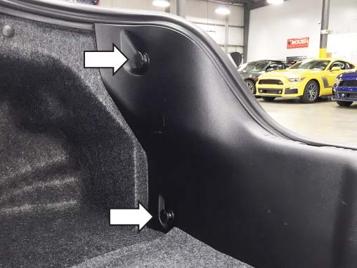
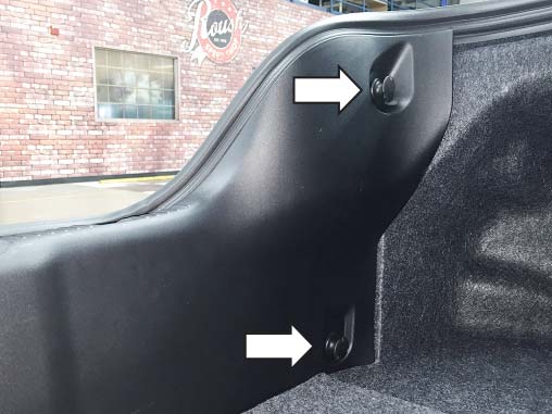
Begin the installation by rst opening the hood and disconnecting the battery (refer to your owner’s manual for guidance). Next open the trunk and remove the spare tire cover panel and rear trunk trim panel. To remove the rear trunk trim panel, loosen the four (4) plastic nuts by hand, push the outer ends forward towards the front of the vehicle and slide the panel upwards to release the remaining clips that are on the backside of the panel.
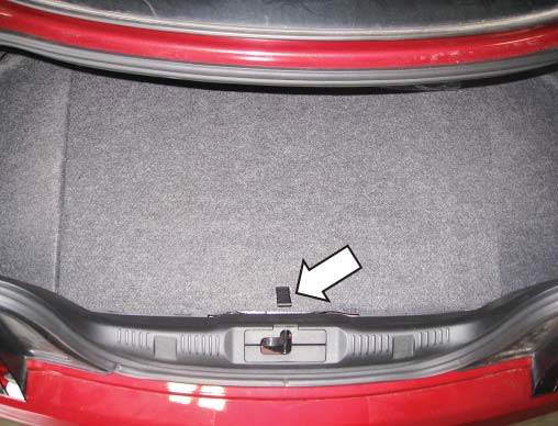
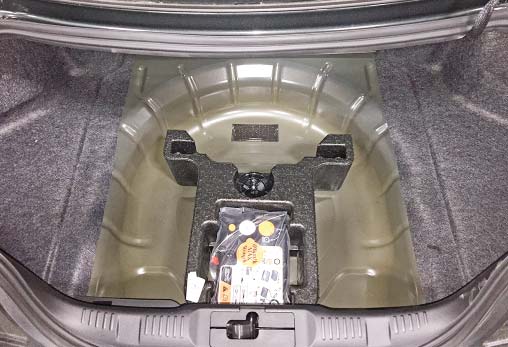
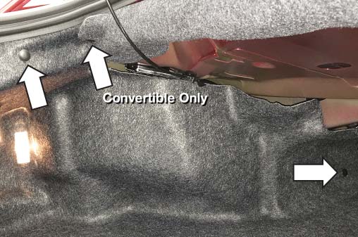
3. Remove two (2) push pins along the driver side trunk carpet if your vehicle is a fastback. If your vehicle is a convertible, then you will need to remove three (3) push pins along the driver side trunk carpet.
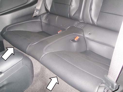
4. Remove the bottom portion of the rear seat by pushing in on the latches that are under the front edge on each side and lifting the seat up.
5. Remove the door sill trim piece by rst lifting up at the front corner and then disengaging the clips along the bottom.
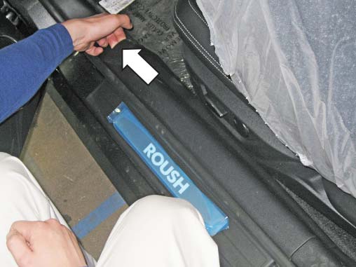
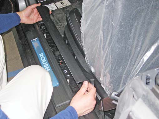
6. Remove the rear quarter panel trim piece by rst removing the seat belt guide trim ring and then rmly pulling inwards along the panel to disconnect the plastic clips along the back.
NOTE: For fastback models, rst release the upper portion of the rear seat and fold it down to gain access to the seat belt guide trim ring.
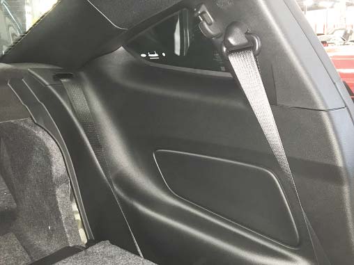
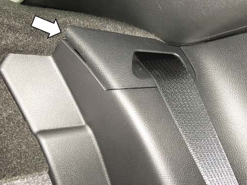
NOTE: For convertible models, after removing the seat belt guide trim ring, remove the top trim piece by rst lifting up at the front and disengaging the clips along the bottom. Now remove the quarter panel trim piece as previously instructed.
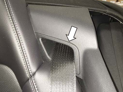
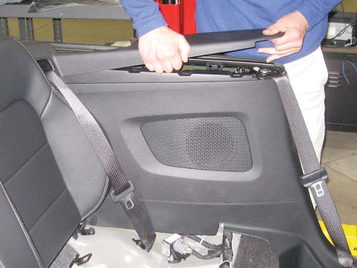
7. Remove the driver side trunk carpet.
NOTE: For fastback models, rst remove the push pin that is located near the driver side rear seat belt.
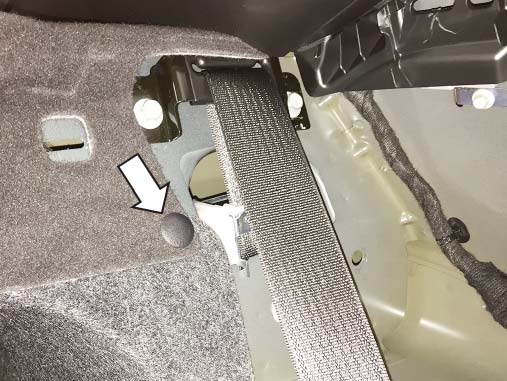
NOTE: For convertible models, rst remove the trunk light that is mounted in the driver side trunk carpet by pressing it out from the back.
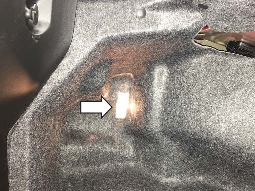
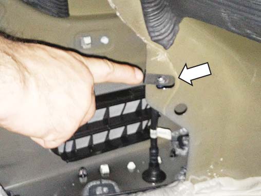
8. Locate the M6 J-Clip (P/N: 95210A175) that is in the Hardware Kit (P/N: 1315-5231AVHK_AA) and install it on the driver side sheet metal in the trunk as shown below. Location for fastback models shown below:
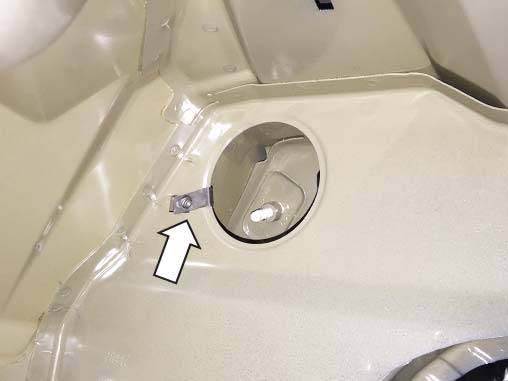
Location for convertible models shown below:
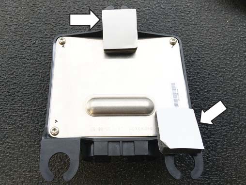
9. Apply the two (2) pieces of foam tape (P/N: 1315-5E260TP) to the back of the active exhaust control module (P/N: 1315-5E260) and locate the included rubber grommet as shown. Location for fastback models shown below:
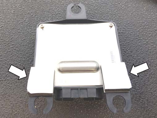
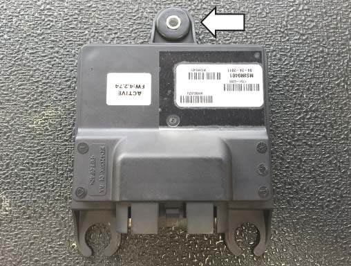
Location for convertible models shown below:
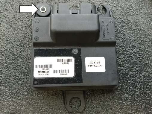
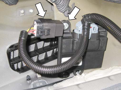
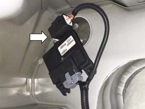
10. Set the active exhaust wiring harness (P/N: 1315- 9L430) in the trunk and locate the large relay. Take the M6 x 31 bolt (P/N: R18020009-00) and insert it through the grommet on the control module followed by the mounting tab on the relay and then insert it into the M6 J-Clip (P/N: 95210A175) that was installed in step 5. Torque the bolt to 10 Nm and then plug the module connector from the wiring harness into the module.
Location for convertible models shown below:
Location for fastback models shown below:
11. Remove the rubber cap that is on the passenger side of the spare tire well. Locate the section of the active exhaust wiring harness (P/N: 1315- 9L430) that has the grommet and feed the two (2) connectors through the hole in the spare tire well that the rubber cap was removed from. Fully seat the grommet from the active exhaust wiring harness into the sheet metal of the trunk oor.
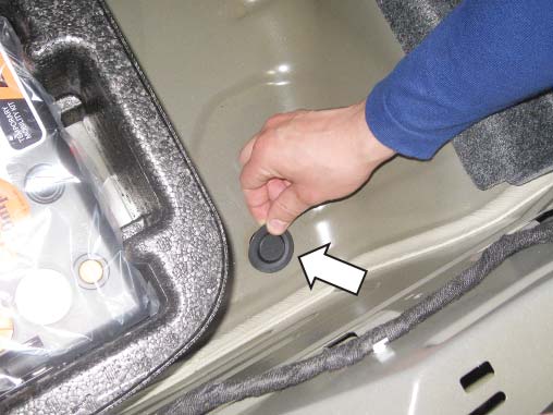
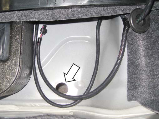
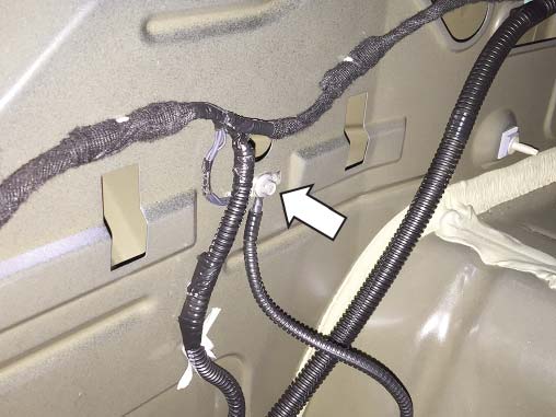
12. Remove the 8 mm bolt from the factory ground at the rear of the trunk as well as the push-in retainer from the factory wiring harness.
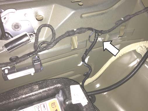
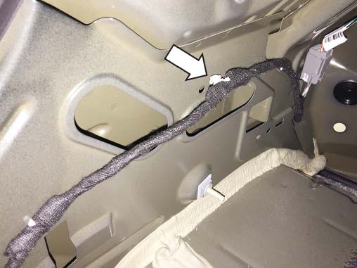
13. Insert the 8 mm bolt into the ring terminal on the active exhaust wiring harness (P/N: 1315-9L430) and then reinstall it with the factory ground into the position it was removed from in step 12
and torque to 2 Nm. Insert the push-in retainer from the factory wiring harness into the ring clip from the active exhaust wiring harness and then reinstall the push-in retainer into the position it was removed from in step 12.
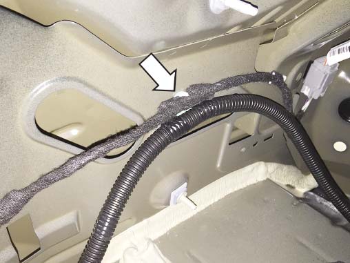
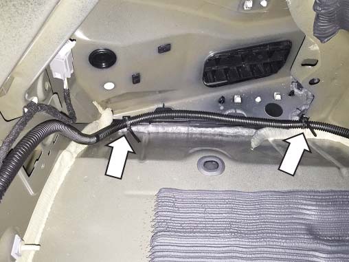
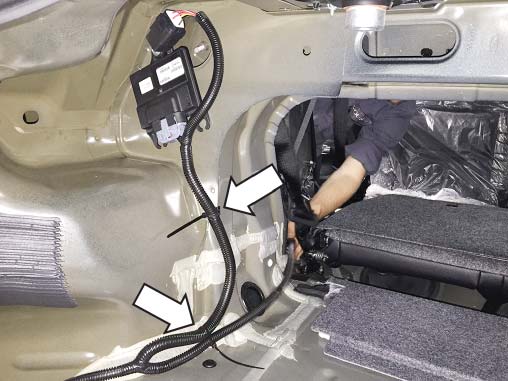
14. Route the wiring harness along the driver side of the trunk into the cabin and secure with both the standard 7" zip ties (P/N: CTUV740) and the zip ties with edge clips (P/N: 156-00865) as shown below. Trim the tails of the zip ties once they are secure.
Re-install the driver side trunk carpet (and trunk light, if equipped). Re-install the rear trunk trim panel by reversing the removal process outlined in step 2. Re-install the spare tire cover panel.
Continue routing the wiring harness along the driver side of the vehicle and secure with the standard 7" zip ties (P/N: CTUV740) as shown.
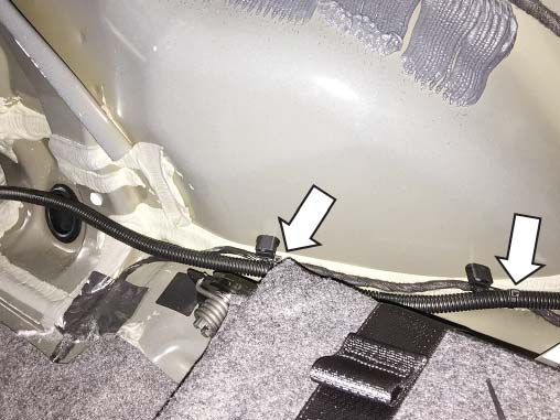
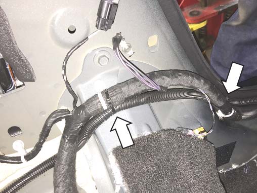
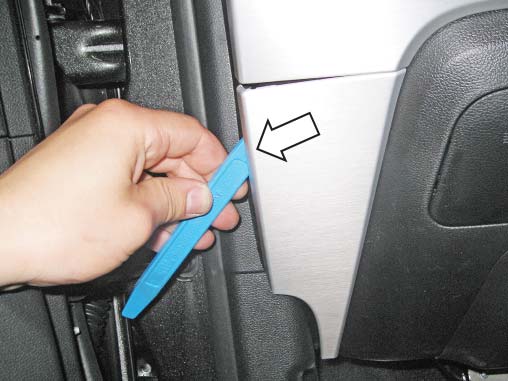
17. Remove the lower driver side dash trim panel with a non-marring trim tool. Gently pry the trim piece out to release the clips on the backside.
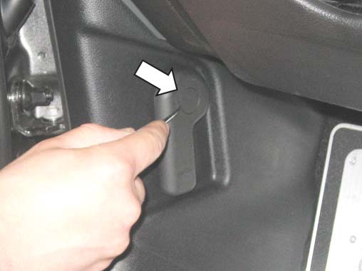
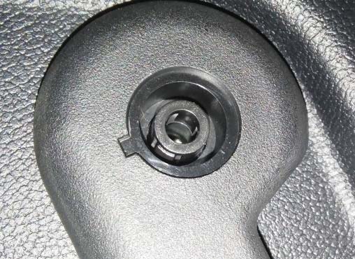
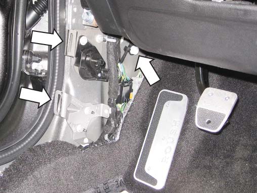
18. Remove the driver side kick panel. Start by prying out the center cap in the hood release handle with a small pick and then releasing the inner tabs with a small at-head screwdriver to remove the handle. There are also two (2) clips along the door jam and one (1) push pin at the front that need to be released in order to remove the panel.
19. Remove the bottom portion of the door seal. Disconnect the electrical connector for the illuminated door sill plates. Remove the two (2) metal clips along the seam in the sheet metal.
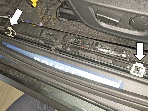
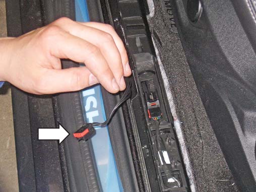
20. Remove the two (2) push pins that secure the carpet to the wire harness housing along the door sill and remove the two (2) 10 mm fasteners that secure the door sill wire harness housing to the vehicle. Pull the housing back to reveal the factory sections of tape and carefully remove or cut each section of tape along the outer edge of the wire harness housing.
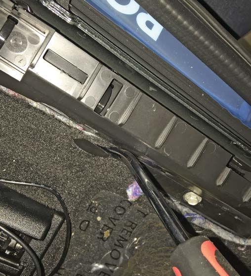
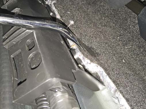
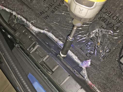
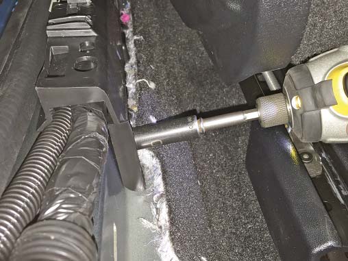
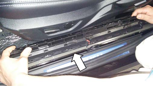
21. Route the active exhaust wire harness along the outside of the factory wiring harness in the wire harness housing. Close the wire harness housing and apply new sections of tape to secure it closed.
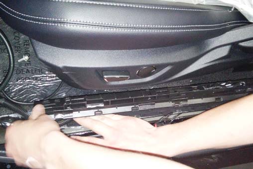
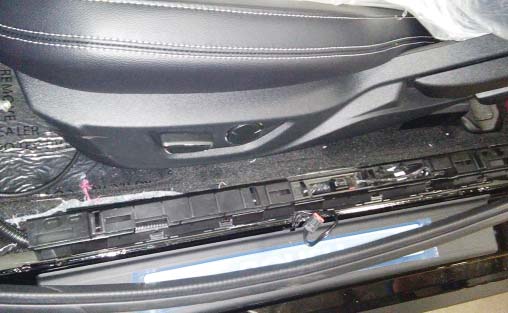
22. Reinstall the two (2) metal clips onto the sheet metal seam that were removed in step 19. Reinstall the two (2) 10mm fasteners that secure the door sill wire harness housing which were removed in step 19 and torque to 2 Nm. Reinstall the two (2) push pins that retain the carpet to the wire harness housing that were removed in step 20.
23. Re-install the rear quarter trim panel and the bottom portion of the rear seat by reversing the process outlined in steps 4 and 6.
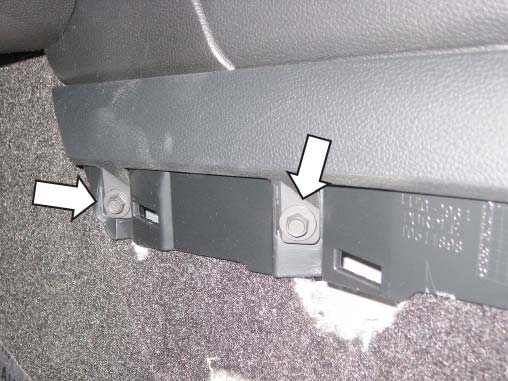
24. Remove the side trim pieces along the center console by lifting the front lower corners and carefully disengage the retaining clips along the back. Remove two (2) 7 mm fasteners on each side of the console once the trim pieces are removed.
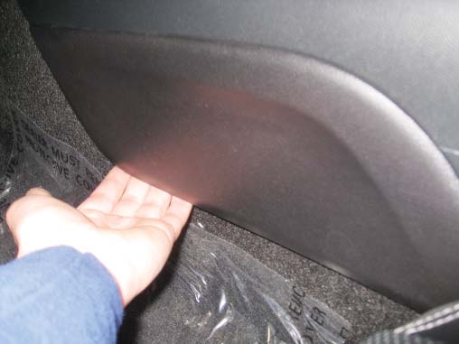
25. Remove the molded rubber tray from in front of the shifter.
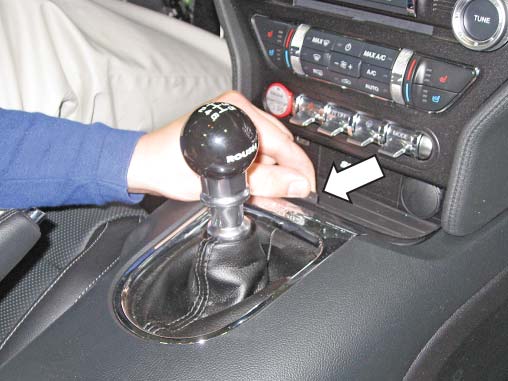
26. Using a non-marring trim tool, gently lift each of the rear corners of the center console and disengage the retaining clips along the bottom from the rear all the way up to the front.
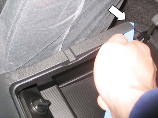
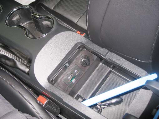
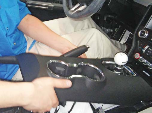
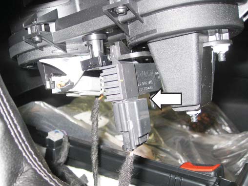
27. With the emergency brake fully engaged, lift the top portion of the center console up and unplug the connectors for the key fob detection circuit and for the cup holder lighting (if equipped).
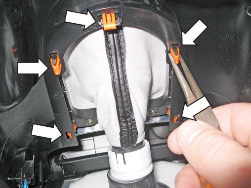
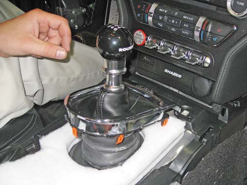
28. Release the clips for the shifter trim bezel and remove the top section of the center console from the vehicle.
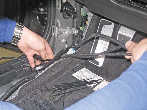
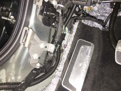
29. Continue routing the wire harness up through the driver side kick panel area and secure as shown below.
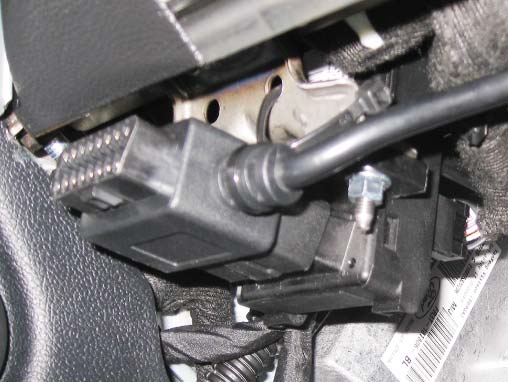
30. Plug the OBDII pass-through connector that is part of the active exhaust wiring harness (P/N: 1315-9L430) into the OBDII connector that is under the dash. Secure the connector with two (2) standard 7" zip ties (P/N: CTUV740) as shown below.
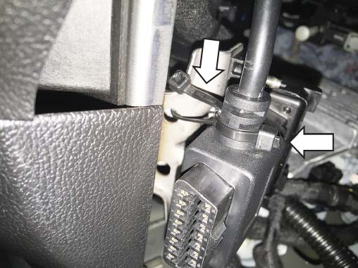
31. Continue routing the wiring harness along the dash structure up through to the center console and secure with the standard 7" zip ties (P/N: CTUV740) as shown below.
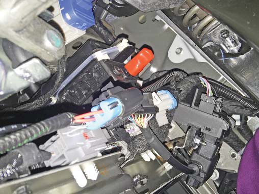
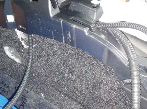
32. Unplug the connector for the 12-volt power outlet that is in the center console. Using a small pick, remove the red locking piece that is in the end of the connector. Carefully lift the tab for the grey with orange wire in the connector and remove the terminal from the connector.
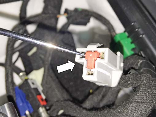
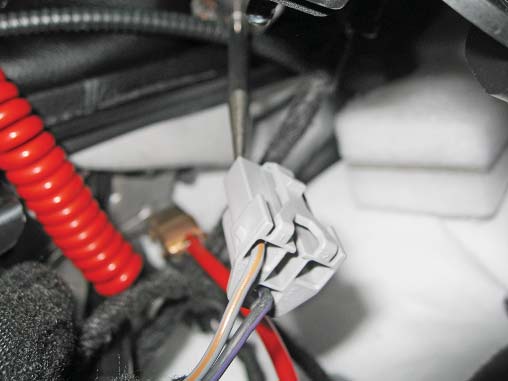
33. Take the yellow lead from the active exhaust wiring harness (P/N: 1315-9L430) that has the same terminal on the end and insert it into the spot in the 12-volt power outlet connector that was de-pinned in step 32. Replace the red locking piece that was in the end of the connector.
34. Remove the rear clip and seal from the new connector that is bagged and taped to the active exhaust harness. Insert the clip and then the seal onto the grey with orange wire that was removed from the 12-volt power outlet connector and then insert into the new connector as shown below.
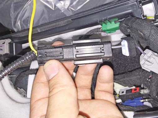
Check to make sure all the connections are fully seated, slide the seal into place as well as the rear clip. Plug the connector into the active exhaust wiring harness (P/N: 1315-9L430) and press the red lock in the front of the connector to lock it in place.
Plug the factory 12-volt power outlet connector back into the 12-volt outlet in the center console and route the active exhaust wiring harness in the center console as shown.
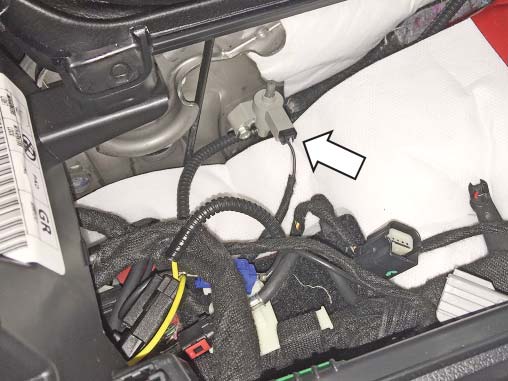
37. Locate the lead on the active exhaust wiring harness with the fuse tap on the end and route it outside of the console along the dash structure up to the passenger side kick panel and secure the harness with standard 7" zip ties (P/N: CTUV740) as shown.
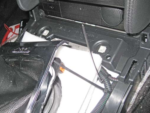
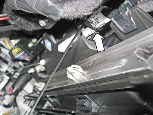
38. Remove the fuse panel cover in the passenger kick panel area and remove fuse #23 (10 amp) from the fuse panel. Plug the 10-amp fuse into the fuse tap that is located in the active exhaust wiring harness (P/N: 1315-9L430). Locate the 10-amp fuse (P/N: ATP-10A) that is part of the hardware kit (P/N: 1315-5231AVHK) and plug that into the additional spot in the fuse tap. Plug the fuse tap into slot #23 that the 10-amp fuse was originally removed from.
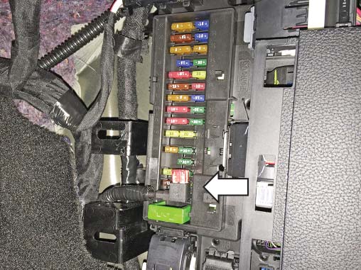
Reinstall the fuse panel cover.
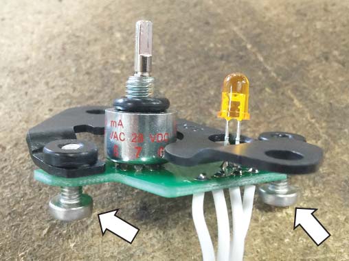
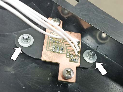
Locate the active exhaust switch (P/N: 1315- 13K724) and install it onto the switch bracket (P/N: 1315-7Z374) with two (2) M4 screws (P/N: 90116A207), torque to 1 Nm. Install the O-ring (P/N: 9262K215) onto the switch post.
Trim out the drill template that is located on the last page of this installation manual.
With the top section of the center console placed in a safe area, tape the drill template into position as shown.
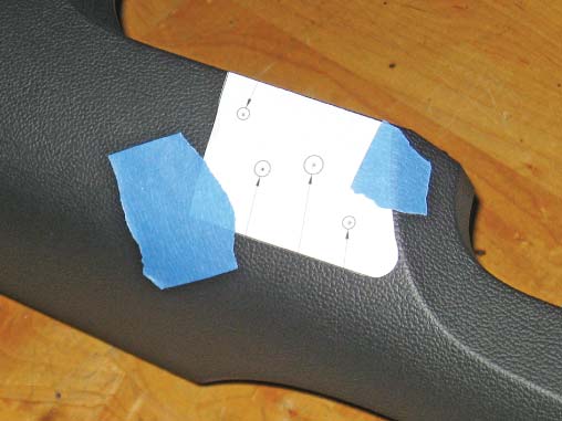
43. Mark the four (4) holes with a center punch and drill them with the appropriate sized drill bits as indicated by the template (1/4").
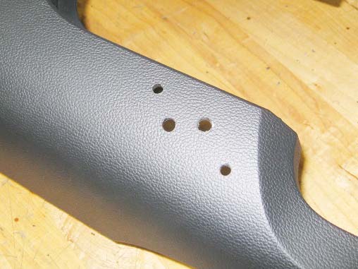
44. Remove the template and insert the studs on the active exhaust switch plate (P/N: 1315-11806) through the holes that were drilled in step 43. Turn the console over and insert two (2) M4 nylon washers (P/N: 91755A215) onto the front stud of the switch plate and (1) nylon washer (P/N: 91755A215) onto the rear stud of the switch plate. Insert the switch and bracket assembly onto the switch plate studs and carefully secure with two (2) 3/16" push nuts. A deep 7 mm socket works well to drive the push nuts onto the studs. Check to make sure the entire assembly is fully seated and that there is no play in any of the components.
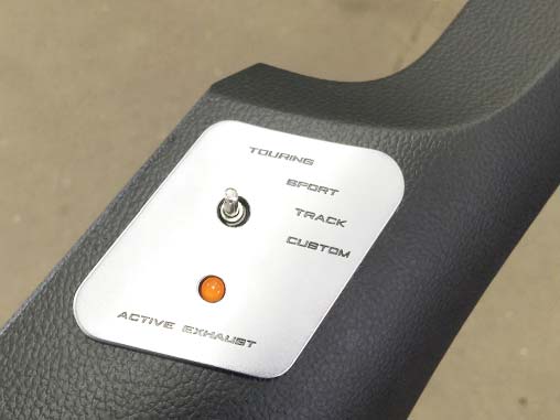
Reinstall the top section of the center console and the side trim pieces by reversing steps 24-28 while being sure to plug the active exhaust switch (P/N: 1315-13K724) into the mating connector in the active exhaust wiring harness (P/N: 1315- 9L430). Torque the 7 mm fasteners to 2 Nm.
Reinstall the driver side kick panel and the lower driver side dash trim panel by reversing steps 17-18.
Reinstall the door sill trim piece that was removed in step 5.
Locate the active exhaust switch knob (P/N: 1315-AVKNOB) and the M3 set screw (P/N: 93245A100) which can both be found in the Hardware Kit (P/N: 1315-5231AVHK) and loosely install the set screw into the threaded hole on the side of the knob.
Insert the knob onto the active exhaust switch post. Align the small at on the switch post to be perpendicular to the set screw. Seat the knob fully onto the switch post and torque the set screw to 1 Nm.
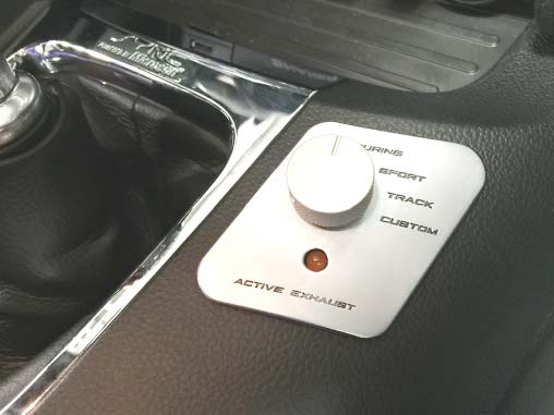
50. Locate the active exhaust valve assemblies (P/N’s: 1315-6506LH and 1315-6505RH) and install
them in place of the straight outlet couplers that are included on the ROUSH Quad Tip Exhaust. Reuse the existing gaskets, nuts, tips and clamps. Torque the nuts to 25 Nm and torque the clamps for the exhaust tips to 47 Nm.
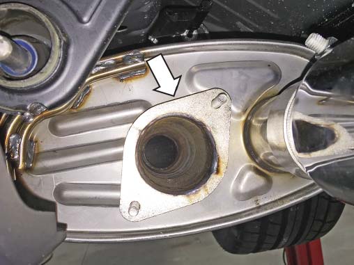
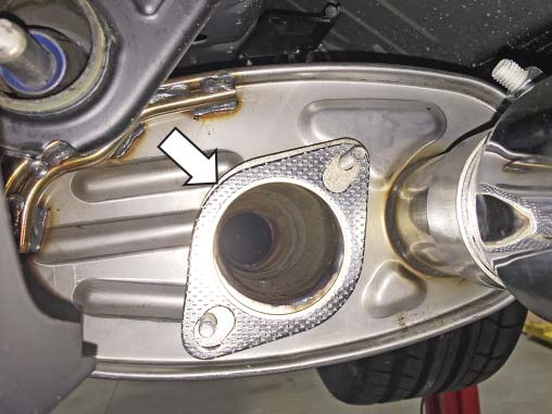
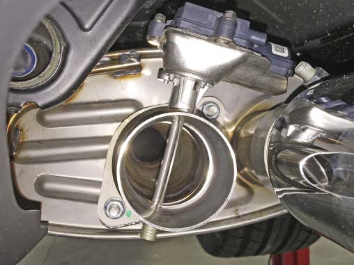
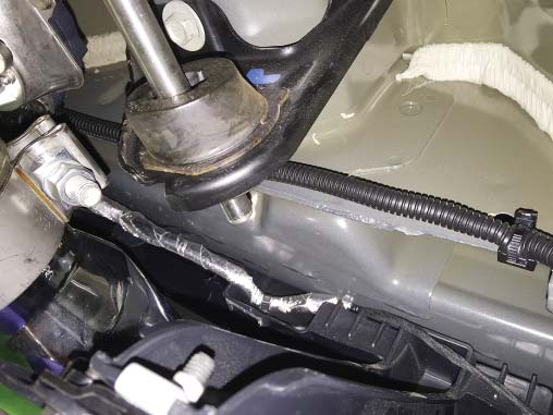
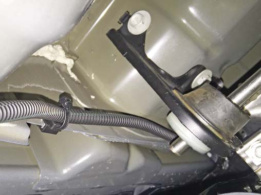
Locate the wiring harness that is routed through the grommet in the trunk oor. Route the short lead to the passenger side valve and the long lead to the driver side valve.
Secure the wiring to the sheet metal edge under the vehicle using the edge clips with zip ties (P/N: 156-00865) as shown below and plug the respective connectors into each valve.
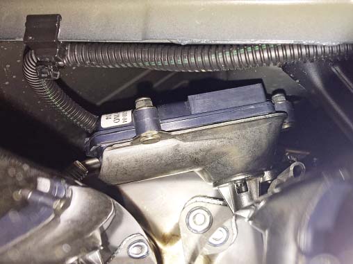
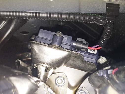
53. Reconnect the battery, start the vehicle and test your new ROUSH active exhaust.
Congratulations, the installation is complete!
