
How to Install an AEM Cold Air Intake on your 2011-2012 Mustang GT
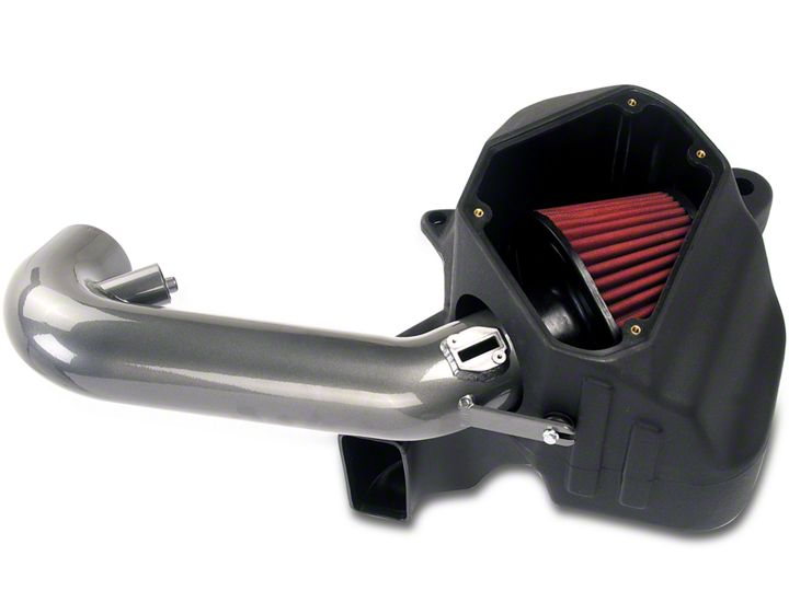
Shop Parts in this Guide
Installation
PARTS LIST
| Desc | Qty. | Part # | |
|---|---|---|---|
| A | Intake Tube | 1 | 2-1445 |
| B | 1/2” Bndhose Clamp, 3.15”-4.00” | 3 | 9456 |
| C | Hose, Silicone 3.50x3” Blk. | 1 | 5-350 |
| D | Airbox Lid; | 1 | 20-8516 |
| E | Air Filter Element | 1 | 21-2145DK |
| F | Elbow, Plastic 5/32” 90 Degree | 1 | 8-152 |
| G | Filter Minder, 10” | 1 | 35-80311 |
| H | Grommet; 1.05” OD, .5”ID, .1875” Groove | 1 | 784642 |
| I | Hose; 5/32”ID X 12”L | 1 | 5-3012 |
| J | Air Box | 1 | 9-0394 |
| K | Bolt, Hex/flange M6-1.0 X 12 | 1 | 1-2038 |
| L | Washer; 1”D X 1/4 Hole Fender | 2 | 08160 |
| M | Grommet, PCV 3/4ID 1 3/8OD | 2 | 784645 |
| N | Mount, Rubber 1” X 6mm Modified | 1 | 1228599-1 |
| O | Nut, M6 Hex Serrated | 1 | 444.460.04 |
| P | Edge Trim, 13” | 1 | 8-4013 |
| Q | Bolt, Socket M4-.7 X 8mm | 2 | 1-2105 |
| R | Washer, #12 Nylon 6/6 | 4 | 1-3001 |
| S | Bolt, Button Head M6-1.0 X 10mm | 4 | 1-112 |

Read and understand these instructions BEFORE attempting to install this product. Failure to follow installation instructions and not using the provided hardware may damage the intake tube, throttle body and engine.
1. Preparing Vehicle
a. Make sure vehicle is parked on level surface.
b. Set parking brake.
c. If engine has run in the past two hours, let it cool down.
d. Disconnect negative battery terminal.
e. Do not discard stock components after removal of the factory system.
2. Removal of stock system

a. Loosen and remove the 4 nuts securing the strut brace.

b. Remove the strut brace.

c. Remove the engine cover by lifting up on it from the front and releasing the 4 snap clips.

d. Unplug the MAF sensor. First pull back on the red latch, then squeeze to release the connector.

e. Release the spring clamp on the sound tube using a pair of pliers.
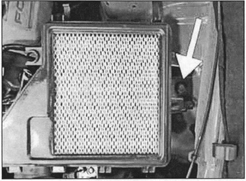
f. Lift up on the rubber support to release it from the OEM airbox.
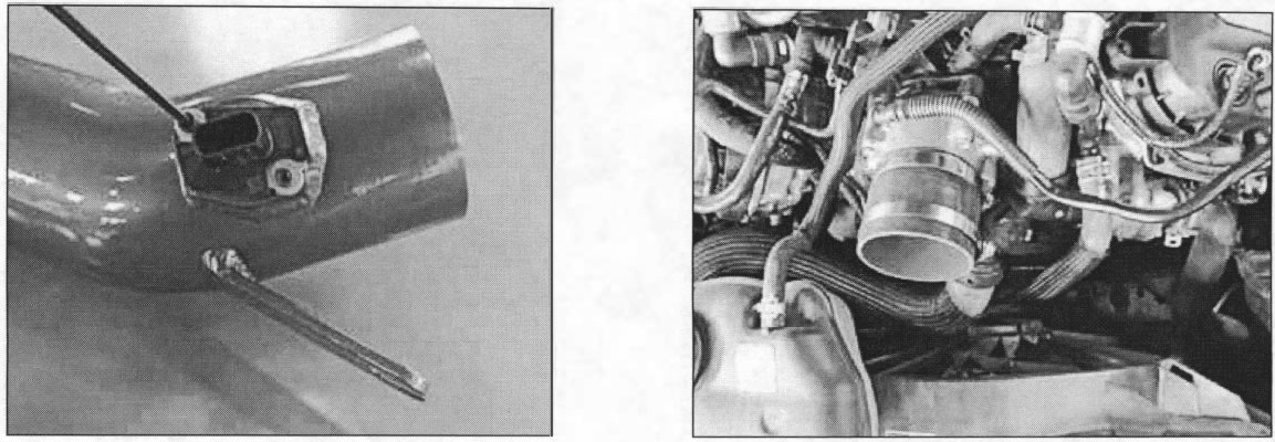
g. Release the crankcase vent tube from the nipple. Slide the gray clip to the side and pull on the connector to release it.

h. Position the sound tube and crankcase vent tube out of the way as shown.

i. Loosen the hose clamp on the throttle body. j. Release the two airbox clips as shown.

j. Unclip the MAF sensor wire harness from the airbox lid.

k. Remove the inlet tube from the throttle body and lift the airbox lid off of the lower airbox. Remove the airbox and inlet tube assembly.
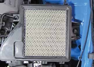
l. Remove the M6 bolt securing the lower airbox, then remove the lower airbox.
3. Installation of AEM® Intake System
a. When installing the intake system, do not completely tighten the hose clamps or mounting hardware until instructed to do so.
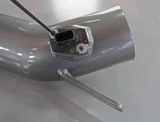
b. Install the MAF sensor into the AEM® intake pipe using the two supplied M4 bolts (#1-2105).
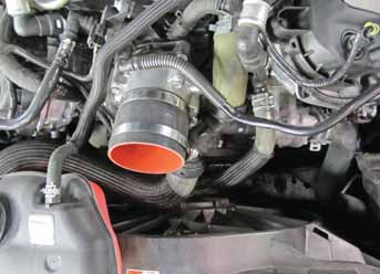
c. Install the 3.5” coupler and two (#9456) hose clamps onto the throttle body. Slide the coupler all the way onto the throttle body, position the hose clamps as shown, and tighten the throttle body-side hose clamp.
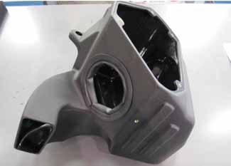
d. Install the rubber edge trim onto the AEM® airbox’s round inlet hole as shown. If necessary, trim the edge trim for proper fitment.
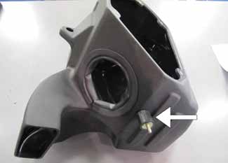
e. Install the rubber mount into the AEM® airbox as shown. Thread the short stud of the rubber mount into the airbox’s threaded hole; hand tighten.
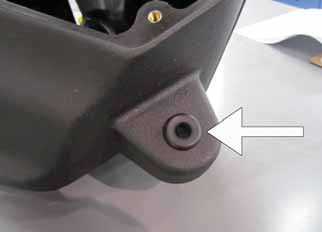
f. Install the supplied grommet (#784642) into the hole in the airbox as shown.
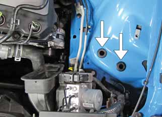
g. Install the two larger grommets (#784645) into the holes in the inner fender area as shown.
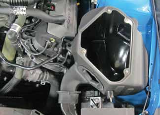
h. Lower the AEM® airbox into position as shown.
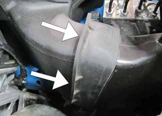
i. Make sure that the large rectangular inlet engages the OEM air scoop.
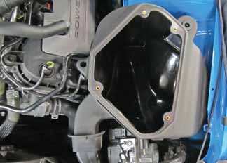
j. Guide the two bosses on the bottom of the AEM® air box into the grommets installed in step 3g.
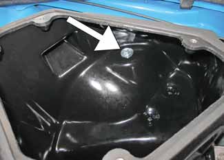
k. Secure the airbox to the vehicle’s frame using the supplied M6 bolt (# 1-2038) and washer (# 08160).
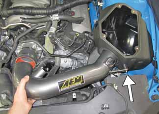
l. Install the AEM® intake pipe as shown. Make sure that the bracket engages the stud on the rubber mount.
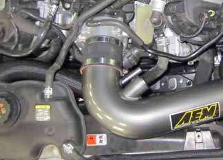
m. Insert the end of the AEM® intake pipe into the throttle body coupler as shown.
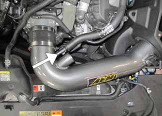
n. Connect the OEM crankcase vent line to the AEM® intake pipe by firmly pressing the connector onto the nipple until it ‘clicks’ into place.
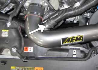
o. Connect the sound tube to the AEM® intake pipe and secure it in place with the OEM spring clamp.
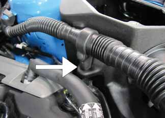
p. Plug the rubber support into the hole of the AEM® airbox as shown.
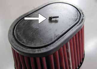
q. Insert the 90 degree plastic connector into the hole located on the air filter top.
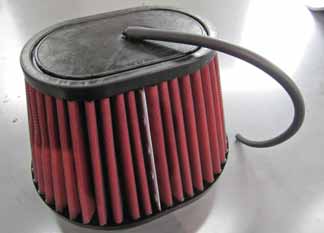
r. Connect the supplied 5/32” hose to the 90 degree connector.
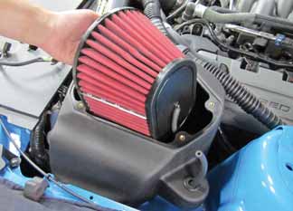
s. Attach a (#9456) hose clamp onto the air filter and lower it into the airbox as shown. Feed the 5/32” hose up through the grommet from inside the airbox.
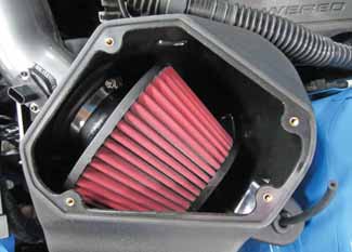
t. Install the air filter onto the end of the AEM® intake pipe and position the filter as shown. Make sure that the pipe is bottomed out on the stops within the air filter. Once proper fitment of the air filter is achieved, secure the (#9456) hose clamp.
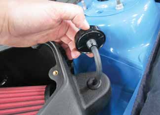
u. Connect the filter minder to the 5/32” hose as shown.
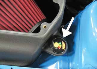
v. Install the filter minder by pressing it into the grommet installed in step 3f.
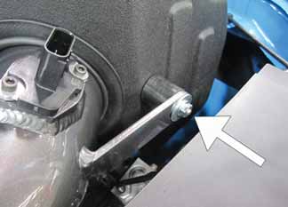
w. Secure the pipe bracket to the rubber mount with a supplied M6 nut (# 444.460.04) and washer (#08160).
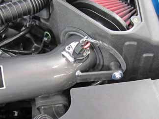
x. Attach the MAF sensor harness connector to the MAF sensor. Adjust the intake pipe for best fitment, then tighten the M6 nut and remaining hose clamp.
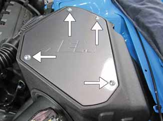
y. Install the AEM® airbox lid using the 4 supplied M6 button head bolts (# 1-112) and nylon washers (#1-3001).
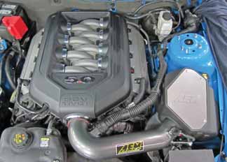
z. Reinstall the engine cover.
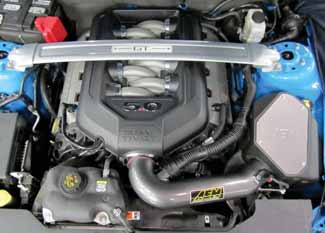
aa. Reinstall the strut brace and tighten all 4 nuts.
4. Reassemble Vehicle
a. Position the inlet pipes for the best fitment. Be sure that the pipes or any other components do not contact any part of the vehicle. Tighten the rubber mount, all bolts, and hose clamps.
b. Check for proper hood clearance. Re-adjust pipes if necessary and re-tighten them.
c. Inspect the engine bay for any loose tools and check that all fasteners that were moved or removed are properly tightened.
d. Reconnect the negative battery terminal and start the engine. Let the vehicle idle for 3 minutes. Perform a final inspection before driving the vehicle.
5. Service and Maintenance
a. It is recommended that you service your AEM® Dryflow™ filter every 20,000 miles for optimum performance. Use AEM Dryflow cleaning kit part # 21-110.
b. Use aluminum polish to clean your polished AEM® intake tube.
c. Use window cleaner to clean your powder coated AEM® intake tube. (NOTE: DO NOT USE aluminum polish on powder coated AEM intake tubes).

