
How to Install AFE Momentum GT Pro DRY S Cold Air Intake (15-17 GT) on your Ford Mustang
Installation Time
1 hours
Tools Required
- 8mm nut driver
- 7mm nut driver
- 10mm deep socket & driver
- 11mm deep socket
- driver
- pliers
- T20 Torx & driver
- panel popper
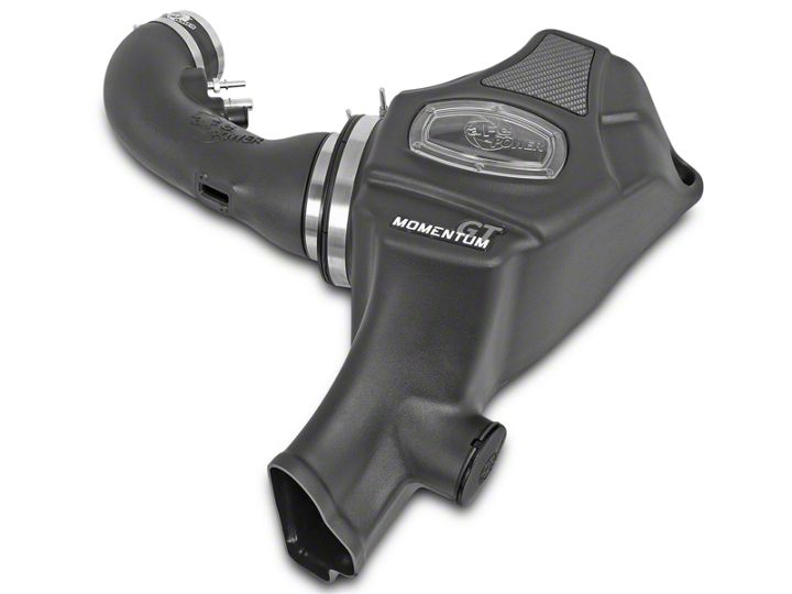
Shop Parts in this Guide
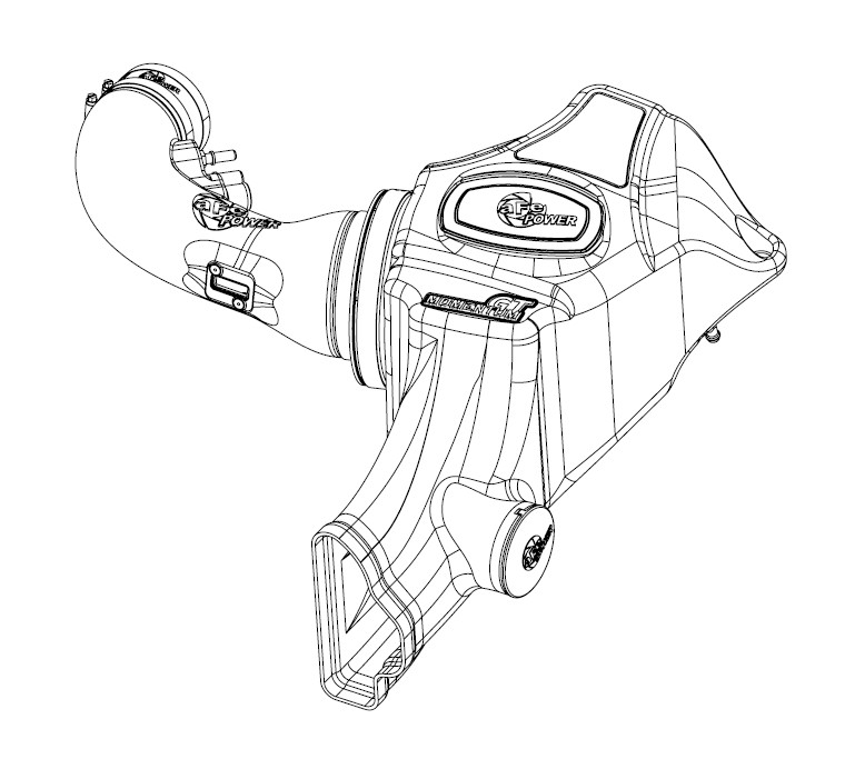
• Please read the entire instruction manual before proceeding.
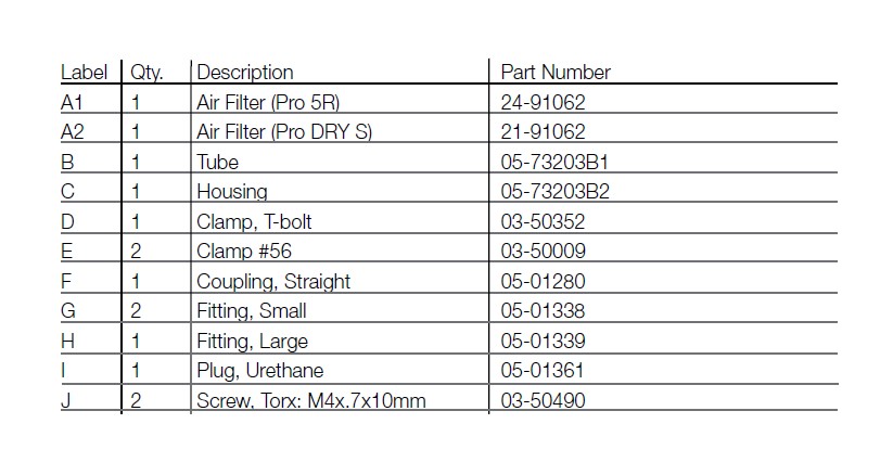
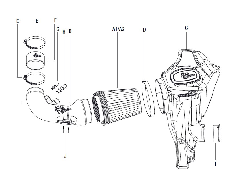
• Ensure all components listed are present.
• If you are missing any of the components, call customer support at 951-493-7100.
• Ensure you have all necessary tools before proceeding.
• Do not attempt to work on your vehicle when the engine is hot.
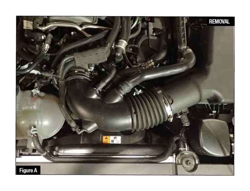
Refer to Figure A for Steps 1-5
Step 1: Remove the engine cover.
Step 2: Loosen the two clamps (7mm nut driver) on the intake tube.
Step 3: Disconnect the three fittings on the intake tube.
Step 4: Slide the spring clamp [pliers] up and disconnect the 1" rubber hose from the intake tube.
Step 5: Remove the intake tube from the vehicle.
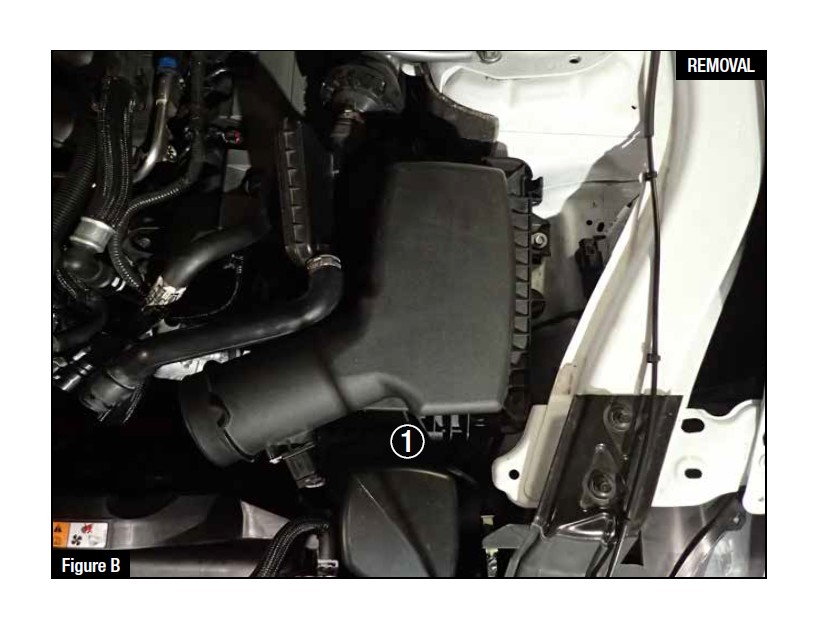
Refer to Figure B for Steps 6-9
Step 6: Remove the bolt (10mm socket) that is securing the housing to the fender.
Step 7: Disconnect the Mass Air Flow (MAF) sensor and unclip the rest of the wire harness from the side of the factory air box.
Step 8: Remove the sound chamber from the air box by pulling straight up on the small box.
Step 9: Pull up on the air box and remove it from the vehicle.
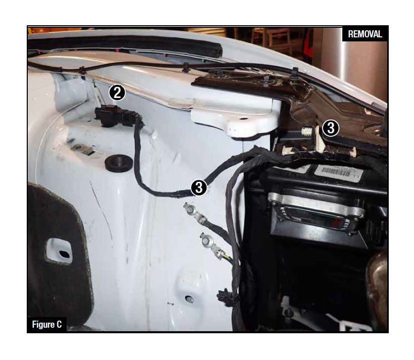
Refer to Figure C for Steps 10-11
Step 10: Relocate the terminated connector, located on the fender well, to the hole nearest the front of the vehicle as shown. 2
Step 11: Disconnect the push clip located further down on the wire harness. This will allow slack to reconnect the MAF sensor later. 3

Refer to Figure D for Steps 12-14
Step 12: Pull out the metal sleeve and rubber grommet from the factory air box.
Step 13: Remove the rubber guide bushing from the factory air box.
Step 14: Transfer the grommet, sleeve, and guide bushing to the new aFe housing.
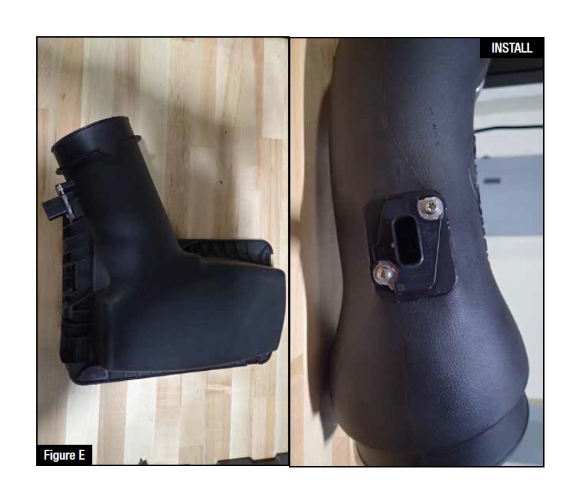
Refer to Figure E for Steps 15-16
Step 15: Remove the MAF sensor from the factory air box using a T20 torx bit.
Step 16: Install the MAF sensor into the new aFe intake tube using the new M4x10mm torx screws.
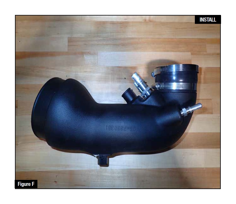
Refer to Figure F for Steps 17-18
Step 17: Pre-install the three aluminum fittings into their proper locations on the intake tube.
Step 18: Install the new silicone coupler onto the small end of the intake tube and put the clamps in place on the coupler but do not tighten the clamps yet.
NOTE: The supplied fittings are NPT threads and will not bottom out in the tube. DO NOT OVER TIGHTEN!
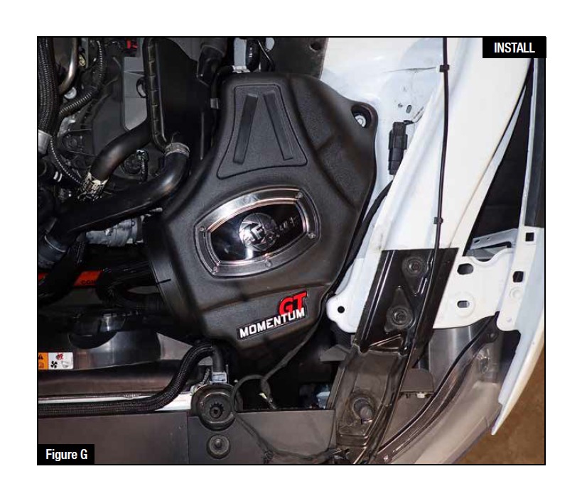
Refer to Figure G for Steps 19-20
Step 19: Install the new aFe housing into the vehicle making sure to line up the front snorkel over the factory air duct. The guide bushing will line up and sit flat on the fender when the snorkel is aligned properly.
Step 20: Use the factory bolt [10mm socket] to secure the new aFe housing in place.
NOTE: Make sure the MAF sensor harness is pulled back out of the way before installing the housing. The wire harness will route over the top of the snorkel.
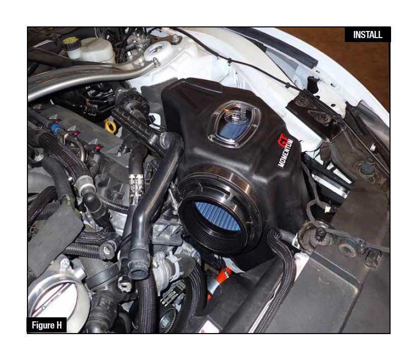
Refer to Figure H for Steps 21-22
Step 21: Place the large t-bolt clamp onto the housing but do not tighten.
Step 22: Install the new aFe air filter into the housing. Make sure the provided clamp is still in place on the filter flange.
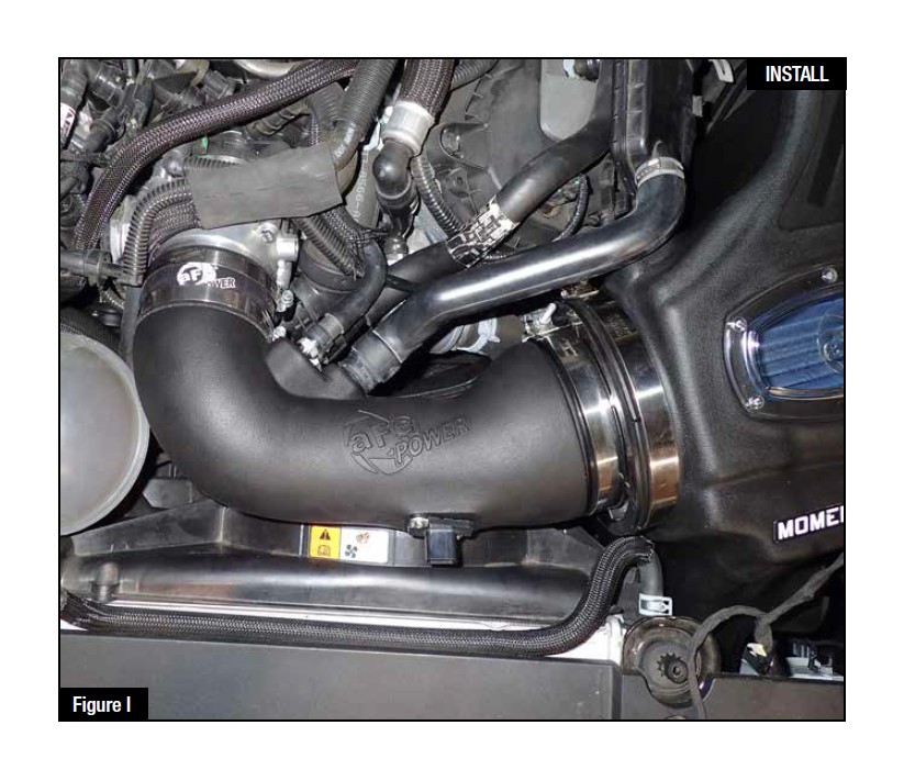
Refer to Figure I for Steps 23-24
Step 23: Install the aFe intake tube into the filter first, connect all of the fittings and hoses, and then slide the coupler end of the tube over the throttle body.
Step 24: Make sure all of the hoses are fully seated on the fittings and that they cannot pull off.
NOTE: The tube that is going to the fitting located on the bottom may need to be rerouted to fit properly.

Refer to Figure J for Steps 25-27
Step 25: Tighten all clamps, reconnect the MAF sensor, and make sure the 1” spring clamp is in place.
Step 26: Reinstall the engine cover.
Step 27: Your install is now complete!!
NOTE: Check all bolts, clamps, and connectors after 200 miles.

