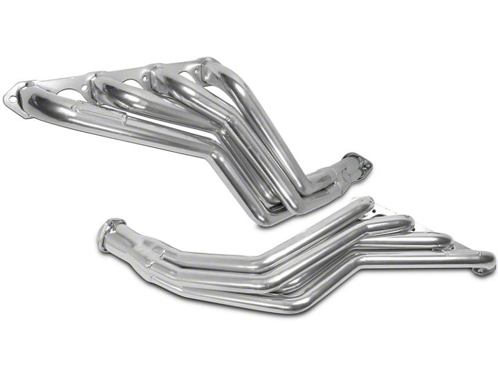
How to Install BBK 1-5/8 in. Ceramic Long Tube Headers (94-95 GT, Cobra) on your Ford Mustang

Shop Parts in this Guide

FITS STANDARD 5 SPEED TRANSMISSION ONLY!!!
Follow these instructions carefully to ensure correct fitment and operation.
STEP 1: Disconnect negative battery terminal.
STEP 2: Place the vehicle on sturdy jack stands or use a drive on lift to raise the vehicle.
STEP 3: Remove the hose clamp at the throttle body, unplug the mass air sensor, if equipped, and remove the complete assembly for clearance.
STEP 4: Remove the AIR injection assembly from the passenger side of the engine compartment.
STEP 5: Working from under the vehicle, unplug the oxygen sensors. Remove the air tube from the stock H-Pipe. Disconnect the H-Pipe from the exhaust manifolds and from the rear flow pipes. Remove stock H-Pipe assembly.
STEP 6: Remove the spark plugs. Remove the stock exhaust manifolds and clean the head surface of any gasket debris. Remove the dipstick tube on driver side. ON PART# 1519 THE EGR TUBE ON THE PASSENGER SIDE EXHAUST MANIFOLD NEEDS TO BE REMOVED BEFORE THE REMOVAL OF THAT EXHAUST MANIFOLD.
STEP 7: Remove the starter. This will allow easier access when installing the passenger side header. The starter can be re-installed after the header is mocked in place with a couple of bolts to hold it.
STEP 8: Remove the motor mount nut on each mount stud that secures the mounts to the frame.
STEP 9: With nuts removed, place a jack under the engine and lift it up to gain needed access to install headers. If needed the engine can also be shifted to the driver side to aid in sliding the passenger side header into place. Be sure to re-install the dipstick tube as you put the driver side header into place. With the headers held into place with a few bolts, lower the engine back down and re-install the motor mount nuts. NOTE!!! Before tightening the motor mounts make sure the engine is sitting evenly and both studs are all the way through the motor mount leaving enough clearance between the steering shaft and header to prevent any rubbing.
STEP 10: Install and tighten all the header bolts. Re-install and tighten the starter
STEP 11: Continue on and re-install all the parts that were removed for installation.
STEP 12: Remove the oxygen sensors from your stock H-Pipe Assembly and install into the provided Bungs in the collector. NOTE!!! Be sure to add a small amount of anti-seize to the top thread of each oxygen sensor using the supplied anti-seize packet. As you thread the oxygen sensor back into the part the anti-seize will spread evenly throughout the threads. To gain wire length, remove the harness from the chassis clips.
• BBK also sells Oxygen Sensor extensions part # 1676

