Top Sellers in Camaro
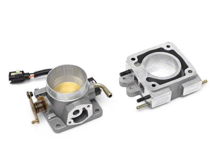
How to install a BBK 70mm Throttle Body w/ EGR Spacer on your 1986-1993 Mustang
Shop Parts in this Guide
Installation
Step 1 Raise hood and allow engine to cool, disconnect negative battery terminal.
Step 2 Loosen both of the air inlet tube clamps located on the throttle body and air cleaner, carefully remove the air inlet tube from the vehicle.
Step 3 Carefully disconnect the throttle position sensor and idle speed control solenoid connectors from the throttle body and disconnect the EGR position sensor connector from the EGR valve.
Step 4 Carefully disconnect the EGR vacuum line from the EGR valve. Loosen the two hose clamps located on the EGR spacer that holds the throttle body coolant hoses and remove hoses. Disconnect throttle linkage.
! CAUTION !
Some coolant may discharge from the throttle body coolant hoses when removed.
Step 5 Remove the four (4) throttle body attaching nuts and carefully remove the throttle body attaching nuts and carefully remove the throttle body and EGR spacer valve assembly from the upper intake manifold studs.
Step 6 For maximum performance with the larger throttle bodies use the matching size EGR spacer and enlarge upper manifold mouth accordingly.
Step 7 Remove the idle speed solenoid and install on the new throttle body. (Use supplied idle solenoid gasket.) Install new EGR valve on new EGR plate. (Use supplied gasket.)
Step 8 Position the following onto the intake manifold studs in order of listing.
- EGR spacer gasket.
- EGR spacer.
- Throttle body gasket.
- Throttle body. Torque throttle body attaching nuts to 12-18 ft.-lbs.
Step 9 Connect the throttle position sensor, EGR position sensor and the idle speed control solenoid. Connect the throttle body coolant hoses and tighten securely. Connect the throttle linkage.
Step 10 Re-install the sir inlet tube onto the throttle body and air cleaner. Tighten the clamps firmly.
Step 11 Set the idle speed by using the following sequence:
1. Turn the ignition switch to the OFF position.
2. Turn the throttle plate hard stop screw control 5 turns clockwise from the fully closed position.
3. Disconnect the idle speed control solenoid connector.
4. Run the engine until it is at operating temperature.
5. Turn the throttle plate hard stop screw counter clockwise until the factory idle speed setting is obtained. Increased idle speed may be required if the engine has been modified.
6. Turn the engine off and reconnect the idle speed control connector.
Step 12 Turn the ignition switch to the ON position but do not start the engine. Using a digital volt/ohmmeter, measure the voltage between the DG/LG and BK/W wires. Be sure the voltage is between 0.8v and 1.0v. If necessary, elongate the mounting holes on the throttle position sensor to obtain this specification.


