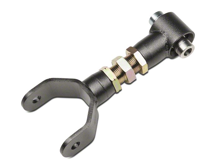
How to install a BMR Adjustable Rear Upper Control Arm - Spherical Bushing on your 2005-2010 Mustang

Shop Parts in this Guide
Installation
NOTE: While this installation can be performed with a jack and jack stands, a service lift is recommended.
Installation:
1. One of the bolts that retain the upper control arm mount is accessed under the rear seat inside the car. Remove the lower section of the rear seat by releasing the two lower clips located at the front of the seat bottom. This can be accomplished by pushing back on the seat until the clips are released, then lift the seat up and pull it out. The upper portion of the seat does not need to be removed.
2. Once the seat is removed, locate the upper control arm mount bolt and remove it using an 18mm socket.
3. Lift vehicle and support with stands under the frame, allowing the rear end to hang. Support rear with jack.
4. Using an 18mm socket, remove the upper control arm bolt at the rear end. The rear will shift slightly on the jack once this bolt is removed.
5. Using an 18mm socket, remove the two remaining control arm mount bolts.
6. It is not possible to remove the upper control arm mount without lowering the fuel tank. Support the tank and loosen the fuel tank straps at the rear of the tank using a 13mm socket (Due to a Ford recall, some cars have a unique 50 IP Torx head bolt in this location. This is an oversized T50 Torx that is only available through Snap-On dealers under part number FTX50TPE) Lower the tank far enough so that the upper mount and control arm can be removed.
7. Once the control arm mount and control arm have been removed, disassemble them using an 18mm socket.
8. When using BMR adjustable control arms, adjust to the approximate OE length. Lubricate the polyurethane bushings (where applicable) and install the BMR control arm into the new upper control arm mount. Insert the new supplied bolt but do not tighten yet.
9. Bolt the BMR control arm mount into the car using the rear lower factory bolts. Tighten to 110 ft/lbs.
10. Insert the OE bolt into the upper front hole located inside the car and tighten to 129 ft/lbs. using an 18mm socket. Reinstall the rear seat.
11. Reposition the fuel tank and tighten the strap bolts to 33 ft/lbs.
12. Rotate the rear end until the mounting hole lines up and insert the bolt.
13. If you are using part number UTCA018, you can tighten both control arm mounting bolts at this time. If using part number UTCA017, the rear end must be loaded before tightening the bolts. To do this, lift the rear to ride height and then tighten the control arm mounting bolts. Tighten both cross-bolts to 129 ft/lbs. NOTE: Failure to load the suspension before tightening these bolts can result in premature bushing failure due to bushing pre-load.
14. Lower vehicle.
ADJUSTING PINION ANGLE – Part #’s UTCA019 and UTCA020
- Make sure the rear end is loaded by either setting the car on the ground or letting the car rest on jack stands positioned under the rear axle. In both cases, the car needs to be as level as possible and the suspension loaded.
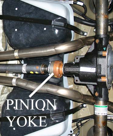
- Place an angle finder on the rear portion of the two piece driveshaft and record the angle. Now place the angle finder on the pinion yoke and record the angle.
- Subtracting one angle from the other results in your pinion angle (Example: -2 rear end angle subtracted from 0 driveshaft angle = -2 degrees)
- Adjust the control arm to achieve the desired angle.
- As a starting point, most cars respond well to the following initial settings: Automatics: 1-2 degrees negative, Manuals: 2-3 degrees negative
- Once pinion angle has been set, apply Loctite to jam nuts and tighten.


