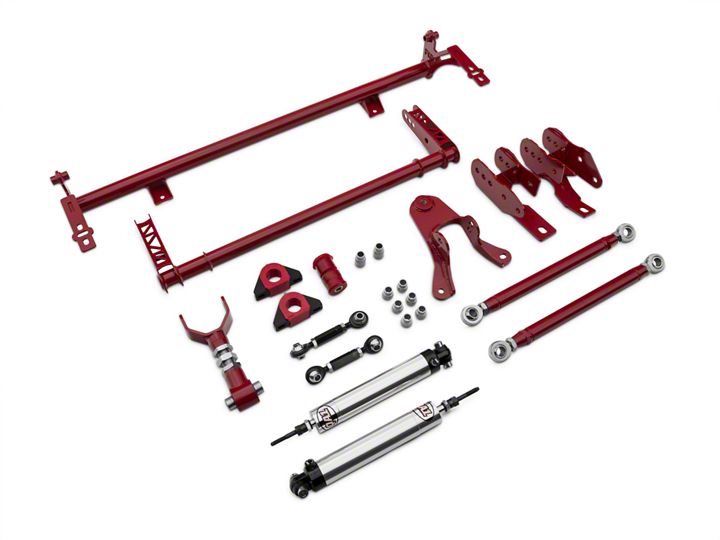
How to Install BMR Drag Race Package (Level 2) - Red on your Mustang
Installation Time
1 hours
Tools Required
- • Floor Jack
- • Snap Ring Pliers
- Snap Ring Pliers
- Jack Stands
- Spanner Wrench Set
- Wrenches (SAE and/or Metric)
- Socket Set (SAE and/or Metric)
- Permatex® Anti-Seize Lubricant
Shop Parts in this Guide
Coil-Over Shock Assembly
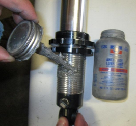
1. Thread the aluminum lock nut (shoulder up) and the spring seat adjuster nut (shoulder up) down to the last thread - NO FURTHER. Now is a good time to lubricate the threads of the shock with Permatex® Anti-Seize lubricant.
2. QA1 highly recommends using Thrust Bearing Kit (QA1 P/N 7888-109) for ease of adjustment. If the thrust bearing kit is used, coat both sides of the washers with Permatex® Anti-Seize lubricant. Install the stainless steel spring seat washer, followed by the bearing and finally, the second washer.
3. If the thrust bearing kit is not used, coat one side of the stainless steel spring seat washer with Permatex® Anti-Seize lubricant. Place the lubricated side of the washer down on the spring seat.
4. With the piston rod fully extended, slide the spring over the shock down to the spring seat adjuster and install the spring cap. Note: xx401 and xx402 shock require 10” springs to be compressed about ½” for installation.
5. Make all ride height changes with the car off the ground and the suspension unloaded. Apply Permatex® Anti-Seize lubricant before making any adjustments to the ride height. Once you have the ride height set, tighten the lock nut against the spring seat adjuster using spanner wrench part number T114W or T115W.
Note: A four wheel alignment should be performed by a qualified alignment shop after any changes to the suspension system.
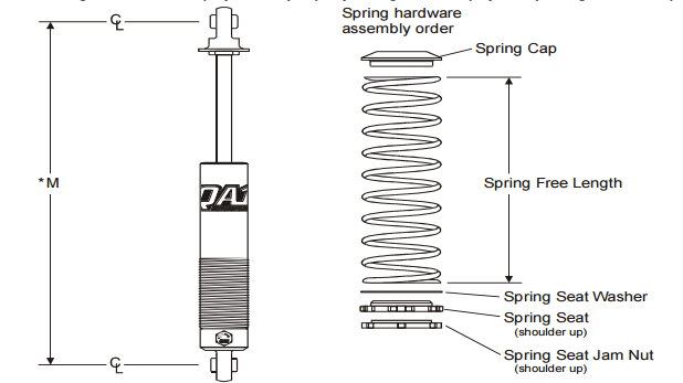
*M - Proper measurement of shock lengths, extended, compressed and shock ride height are taken from the center of the top shock mount to the center of the bottom shock mount. Compressed and extended lengths measured from the center of loop(s) and/or shaft shoulder and/or stud shoulder. If measuring from mounting surface to mounting surface, deduct 5/8“ for each mounting surface to allow for the bushings.

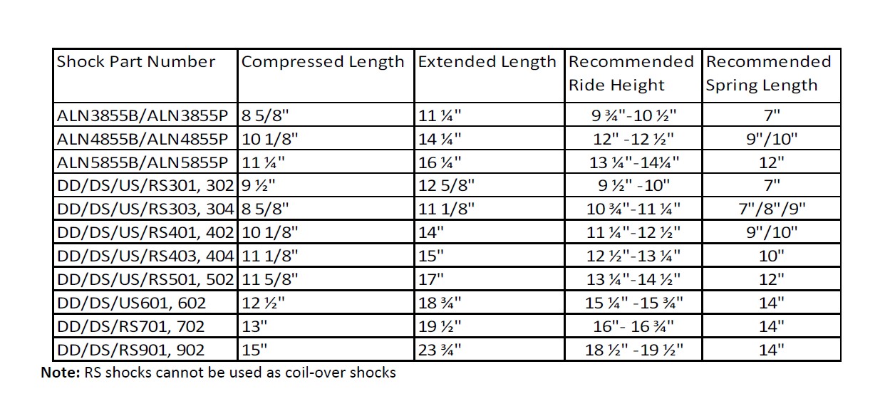
Shock Valving Adjustments
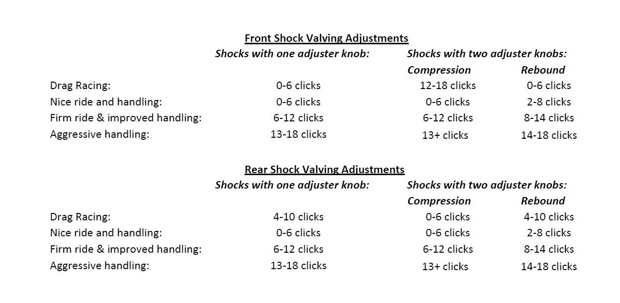
QA1 shocks have 18 damping settings per knob. There are 6 clicks per revolution of each knob, and each knob has 3 complete revolutions. The knob set fully counter clockwise is the softest setting - start your adjustments from that point.
Recommended base settings to begin testing with are as follows:
