Top Sellers in Corvette
How to Install BMR Lower Torque Box Reinforcment Plates - Raw (79-04 All) on your Ford Mustang
Tools Required
- Jack and jack stands
- Ratchet
- Sockets: 18mm, 19mm, 9/16"
- Wrenches: 18mm, 19mm, 9/16"
- Drill with 3/8" drill bit and step bit
- Wrenches: 18mm, 9/16", 21mm (1994+ only)
- Sockets: 18mm deep, 9/16" with extension, T50 torx bit, 8mm (1994+ only)
- Drill with 3/8" bit
- Flathead screwdriver
- Rust preventative paint
- Crescent wrench or pliers (1994+ only)
- Body saw or cutoff wheel (1994+ only)
Shop Parts in this Guide
Installation:
1. Raise vehicle and place jack stands under frame rails. Use the jack to support the rear end.
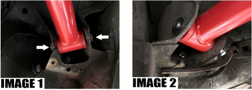
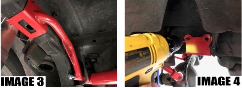
2. Using 18mm socket and wrench, remove upper control arm bolts as shown in IMAGE 1.
3. Insert supplied 12mm upper control arm bolt as shown in IMAGE 2.
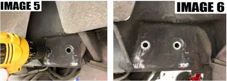
4. Install supplied 7/16" washer and position reinforcement brace as shown in IMAGE 3, followed by supplied 1/2" washer and 12mm nut.
5. Using reinforcement brace as a template, drill two 3/8" holes as shown in IMAGE 4.
6. Remove reinforcement brace to allow access to drilled holes.
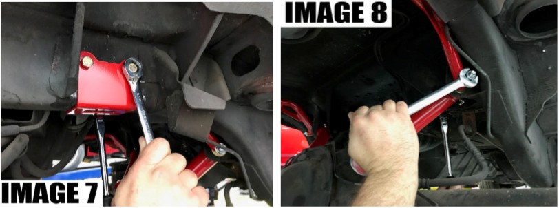
7. Using step bit, open outside hole to 9/16" as shown in IMAGE 5.
8. Insert supplied sleeves as shown in IMAGE 6.
9. Reinstall reinforcement brace.
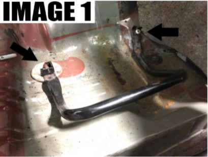
10. Using 9/16" socket and wrench, bolt in place using supplied 3/8" bolts, washers, and nuts as shown in IMAGE 7.
11. Using 19mm socket and wrench, tighten upper control arm mounting bolt as shown in IMAGE 8.
12. Lower vehicle.
TBR004 79-04 MUSTANG UPPER AND LOWER TORQUE BOX REINFORCEMENT
NOTE: Reinforcement plates are supplied bare to give the option of welding the plates in. If you don't plan to weld the plates, paint the plates before installing with a rust preventative paint.
Installation:
1. Remove rear seat by pulling the front of the seat upward.
2. Remove rear seat frame using an 18mm socket and T50 torx bit shown in IMAGE 1. NOTE: Seat frame may differ based on year of vehicle.
3. Remove rubber floor plugs using flathead screwdriver.
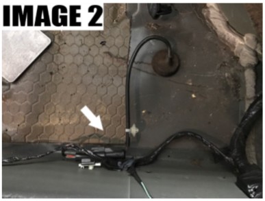
NOTE: Later models have ABS wiring routed through floor plug. Unplug the ABS harness as shown in IMAGE 2 and trim rubber plug to fit between upper and lower plate.
4. Lift rear of vehicle and place on jack stands.
On 1994+ models refer to steps 5 - 7.
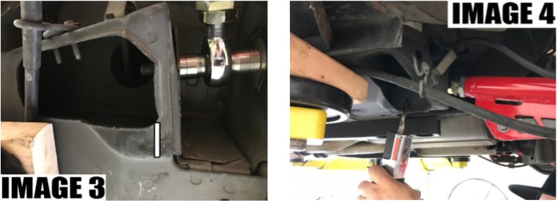
5. On later model vehicles, you may have to trim back material to allow the lower reinforcement plate to fit as shown in IMAGE 3 and 4.
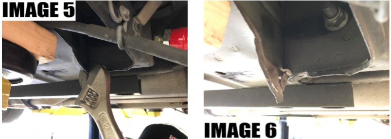
6. Using a crescent wrench, pry the material back to allow the plate to fit as shown in IMAGES 5 and 6.
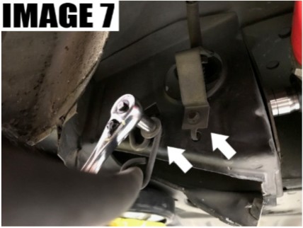
7. Remove two 8mm bolts holding E-brake and ABS harness as shown in IMAGE 7.
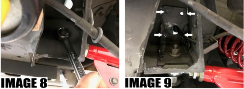
8. Using the 18mm socket and wrench (79-93) or 18mm socket and 21mm wrench (94-04), remove the nut from the lower control arm bolt but leave the bolt in place as shown in IMAGE 8.
9. Position lower plate as shown in and bolt in place. Drill four 3/8" holes as shown in IMAGE 9.
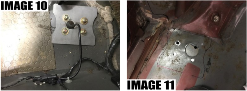
8. Place the upper plate in position as shown in IMAGE 10. (NOTE: If welding upper plates, mark the position of the plates and clean the area to be welded as shown in IMAGE 11.)
9. Using the 9/16" socket and wrench, bolt the upper plate in using the supplied hardware.
If welding, continue to steps 10 - 12. NOTE: If welding plates, use caution not to melt wiring harness or grommet.
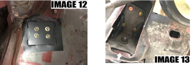
10. Weld upper plate as shown in IMAGE 12.
11. Weld lower plate in the relief area as shown in IMAGE 13.
12. Mask off and paint plates and welded area.
