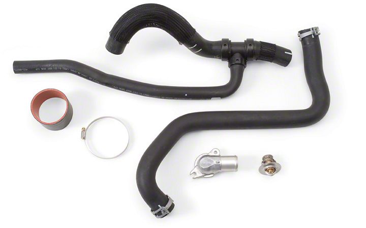
How to install a Edelbrock Cooling System Upgrade Kit on your 2005-2006 GT Mustang

Shop Parts in this Guide
Installation
Please study these instructions carefully before installing your new supercharger. If you have any questions, do not hesitate to contact our Technical Hotline at: (800) 416-8628 from 7:00 am to 5:00 pm, Monday through Friday, Pacific Standard Time.
DESCRIPTION: This kit includes supplemental hardware for installing the #1580/#1585 E-Force Supercharger Systems on 2005 & 2006 model year Mustangs. These components are required for installation and should be purchased before beginning the supercharger installation.
INSTALLATION: Vehicles that require the #15804 kit should refer to the cooling system portion of the #1580/#1585
Installation Instructions for the proper installation procedure for the thermostat and related components. The steps listed below detail the procedure for removing the hydrocarbon trap from the factory air tube and installing it in the silicone elbow supplied with the E-Force Supercharger. This procedure is required to maintain compliance with the California Air Resources Board Executive Order that authorizes installation of the #1580 kit on pollution controlled vehicles.
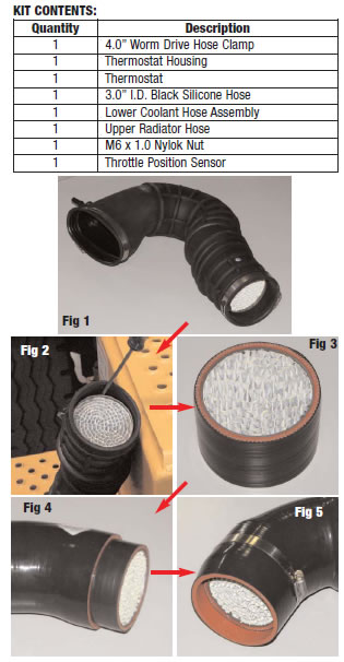
1. Remove the hydrocarbon trap from the factory air tube (Fig 1). The easiest way to do this is to carefully cut the air tube and remove the trap. If you would prefer to keep the air tube intact, it is possible to use one or more flathead screwdrivers to pry the inside lip of the air tube away from the carbon trap (Fig 2), then use a pair of needle nose pliers to grab the metal housing of the trap and work it back and forth to separate it from the tube.
2. Once the trap has been removed from the factory air tube, press it into the short silicone tube supplied with the #15804 kit until both edges are flush (Fig 3).
3. Spray the inside of the silicone elbow supplied with the #1580 supercharger system with silicone spray to facilitate installation then push the hydrocarbon trap into the elbow (Fig 4). Continue pushing the trap into the elbow until there is a gap of roughly 1/2” from the end to the trap.
4. Secure the location of the carbon trap by installing and tightening the supplied hose clamp around the silicone tube where the trap is located (Fig 5). The silicone elbow can now be installed as described in step #154 of the #1580/#1585 Installation Instructions.


