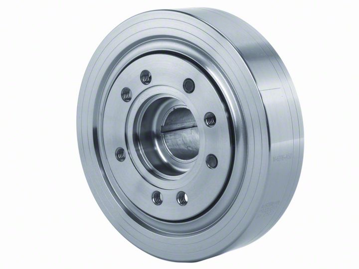
How to install a Ford Racing Steel Harmonic Balancer on your 1981-1993 Mustang

Shop Parts in this Guide
Installation
Step 1: Engine must be completely cold. Drain coolant.
Step 2: Remove water pump. The M-6316-A50 damper is larger in diameter than most production dampers and may interfere with the water pump during damper installation. Rotate engine by hand until timing pointer indicates 0 degrees TDC.
Step 3: Remove original damper carefully using a puller or removal tool.
Step 4: The 302 engine family has used several different timing pointer locations. Most applications will have a timing pointer at the 11 o’clock position. The Ford Racing damper has one set of timing marks for 11 o’clock position. With the crankshaft keyway at the 12 o’clock position, the #1 piston is at TDC. In this position, the timing pointer should point to the 0° mark on the damper. For a quick check prior to installation, compare the timing marks on the original damper with the marks on the Ford Racing damper to determine if is correct for your application. If it looks like the pointer will not line up with the 0° line, see Step 17.
Step 5: Highlight the degree mark for your initial timing setting with paint or grease pencil (white or yellow are easiest to see) for future timing location identification.
Step 6: Inspect the crankshaft post to ensure there are no burrs or rust. If required, polish with a very fine emery cloth. Check leading edge of crank for appropriate chamfer. If required, chamfer as necessary using a file and emery cloth.
Step 7: Measure the crank snout OD and the Damper ID (at the minimum section). Accurate measurements with both parts at the same temperature are essential. Subtract the damper ID from the crank snout OD to determine the interference fit. Recommended fit is .0002" to .0012". If the interference is excessive (too tight), have the damper hub ID honed to bring the fit to spec. Most automotive machine shops are equipped to perform the honing operation. If the fit is too loose, call the Tech Line at (800) 367-3788.
Step 8: Examine the key. If it is damaged or loose in the keyway groove of the crankshaft, install a new key.
Step 9: Replace the front timing cover seal as necessary.
Step 10: Smear the crankshaft post and the timing cover oil seal lip with clean engine oil.
Step 11: Immerse the damper in boiling water for 15 minutes. This will expand the hub of the damper to make installation easier.
Step 12: Remove the damper from the boiling water. Oil the hub ID and (using insulated, heat-proof gloves) quickly slip the damper on the crank post with the damper keyway aligned with the crank key.
Step 13: Using appropriate damper installation tool, install damper as quickly as possible. Install damper bolt and washer and torque to 90 ft./lbs. DO NOT ALLOW THE DAMPER TO COOL BEFORE INSTALLATION IS COMPLETE.
Step 14: Recheck torque after the damper has cooled completely.
Step 15: The 302 engine family has used many different styles of crankshaft dampers with various pulley spacings and bolt hole combinations. Ford Racing offers pulley spacers to properly position the crank pulley. Please see the chart below for your application.
Step 16: Before reinstalling the water pump, ensure a minimum of 1/8" clearance exists between the damper inertia ring and the pump housing. WARNING: Some cast iron water pumps have a casting rib, which must be ground off to clear the damper.
Step 17: Check pulley alignments and check clearance for all components before restarting engine. If you have difficulty installing your Ford Racing damper, please call the Ford Racing Tech Line at (800) 367-3788.
NOTE: Your Ford Racing damper is correctly balanced at the factory. Should your engine be dynamically balanced by a balancing shop, no material is to be added or removed from the damper.

NOTES:
1979 and earlier 351W with .917" SVO crank sprocket can use the M-8510-A351 spacer if .070" is machined from the rear of the damper hub.
Early 3-bolt crank pulleys generally bolt directly to the damper (damper is drilled for 3- and 4-bolt patterns). However, sheave alignment should be checked and the pulley shimmed as necessary to correct any misalignment.

