FREE 1 to 3-Day Delivery on Orders $119+ Details
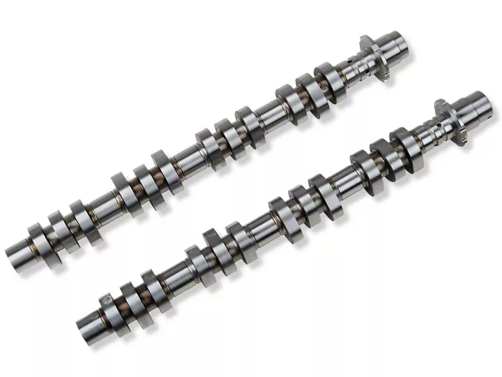
How to install a Ford Racing Hot Rod Performance Camshafts on your 2005-2010 Mustang
Shop Parts in this Guide
Installation
NOTES:
- Purchase new VCT solenoid attachment bolts (as they are not reusable) and Silicon Gasket Sealant from a Ford Dealer. It is not recommended to use any other gasket sealant.
- If doing the work in vehicle, purchase the special service tools required in the service procedures below from a Ford Dealer.
a. The Wedge Tool is needed to hold the timing chain in place so the front cover does not have to be removed. This will save you a lot of time and work if you are working on an engine in a vehicle.
b. If you are doing a new engine build-out of a vehicle, you will not need these tools.
- Follow service procedures to remove ignition coils, oil level indicator, valve covers and camshafts.
- Replace camshafts with Ford Racing camshafts:
a. RH camshaft p/n: XE-6251-309994
b. LH camshaft p/n: XE-6C255-309995
- Follow service procedure to install Ford Racing camshafts, valve covers, dipstick, ignition coils and air induction system.
- Verify there are no oil or air leaks and all electrical connections are made.
- Have a qualified person recalibrate the PCM to realize maximum performance improvement.
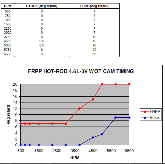
Reference data for calibration:
Production cams 12 mm lift cams
IVO BTDC: 15 49
IVC ABDC: 53 51
Total duration: 248 280
EVO BBDC: 80 97
EVC ATDC: 19 19
• Camshaft timing is controlled by the PCM. The PCM must be calibrated for optimum performance.
Installation
NOTES:
- Purchase new VCT solenoid attachment bolts (as they are not reusable) and Silicon Gasket Sealant from a Ford Dealer. It is not recommended to use any other gasket sealant.
- If doing the work in vehicle, purchase the special service tools required in the service procedures below from a Ford Dealer.
a. The Wedge Tool is needed to hold the timing chain in place so the front cover does not have to be removed. This will save you a lot of time and work if you are working on an engine in a vehicle.
b. If you are doing a new engine build-out of a vehicle, you will not need these tools.
- Follow service procedures to remove ignition coils, oil level indicator, valve covers and camshafts.
- Replace camshafts with Ford Racing camshafts:
a. RH camshaft p/n: XE-6251-309994
b. LH camshaft p/n: XE-6C255-309995
- Follow service procedure to install Ford Racing camshafts, valve covers, dipstick, ignition coils and air induction system.
- Verify there are no oil or air leaks and all electrical connections are made.
- Have a qualified person recalibrate the PCM to realize maximum performance improvement.
Reference data for calibration:
Production cams 12 mm lift cams
IVO BTDC: 15 49
IVC ABDC: 53 51
Total duration: 248 280
EVO BBDC: 80 97
EVC ATDC: 19 19
• Camshaft timing is controlled by the PCM. The PCM must be calibrated for optimum performance.
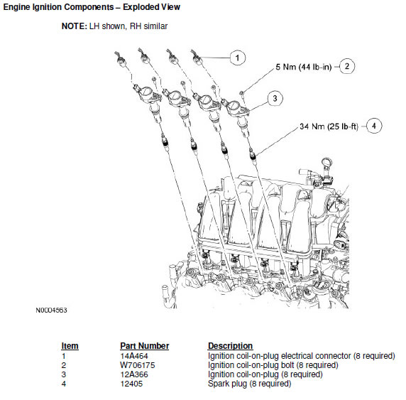
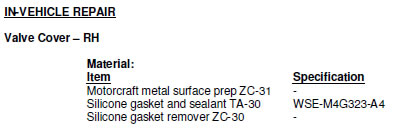
REMOVAL AND INSTALLATION:
Ignition Coil-on-Plug
Material:
Item Specification
Silicone brake caliper grease and dielectric compound XG-3-A ESE-M1C171-A
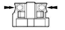
STEP 1: Disconnect the ignition coil electrical connectors.
STEP 2: Remove the ignition coil bolts.
- To install, tighten to 5 Nm (44 lb-in).
STEP 3: NOTE: When removing the ignition coils, a slight twisting motion will break the seal and ease removal. Remove the ignition coils.
STEP 4: To install, reverse the removal procedure.
- Apply a light film of brake caliper grease to the inside of the coil boot before installation.
REMOVAL AND INSTALLATION:
Ignition Coil-on-Plug
Material:
Item Specification
Silicone brake caliper grease and dielectric compound XG-3-A ESE-M1C171-A
STEP 1: Disconnect the ignition coil electrical connectors.
STEP 2: Remove the ignition coil bolts.
- To install, tighten to 5 Nm (44 lb-in).
STEP 3: NOTE: When removing the ignition coils, a slight twisting motion will break the seal and ease removal. Remove the ignition coils.
STEP 4: To install, reverse the removal procedure.
- Apply a light film of brake caliper grease to the inside of the coil boot before installation.
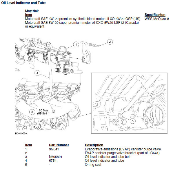
REMOVAL AND INSTALLATION:
STEP 1: With the vehicle in NEUTRAL, position it on a hoist. For additional information, refer to Section 100-02.
STEP 2: Detach the evaporative emissions (EVAP) canister purge valve from the bracket and position aside.
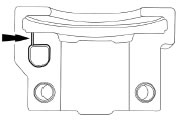
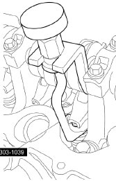
STEP 3: Remove the oil level indicator and tube bolt.
- To install, tighten to 10 Nm (89 lb-in).
STEP 4: Remove the oil lever indicator and tube from the cylinder block.
- Discard the O-ring seal.
STEP 5: NOTE: Lubricate the new oil level indicator tube O-ring seal with clean engine oil prior to installation.
- To install, reverse the removal procedure.
REMOVAL AND INSTALLATION:
STEP 1: With the vehicle in NEUTRAL, position it on a hoist. For additional information, refer to Section 100-02.
STEP 2: Detach the evaporative emissions (EVAP) canister purge valve from the bracket and position aside.
STEP 3: Remove the oil level indicator and tube bolt.
- To install, tighten to 10 Nm (89 lb-in).
STEP 4: Remove the oil lever indicator and tube from the cylinder block.
- Discard the O-ring seal.
STEP 5: NOTE: Lubricate the new oil level indicator tube O-ring seal with clean engine oil prior to installation.
- To install, reverse the removal procedure.
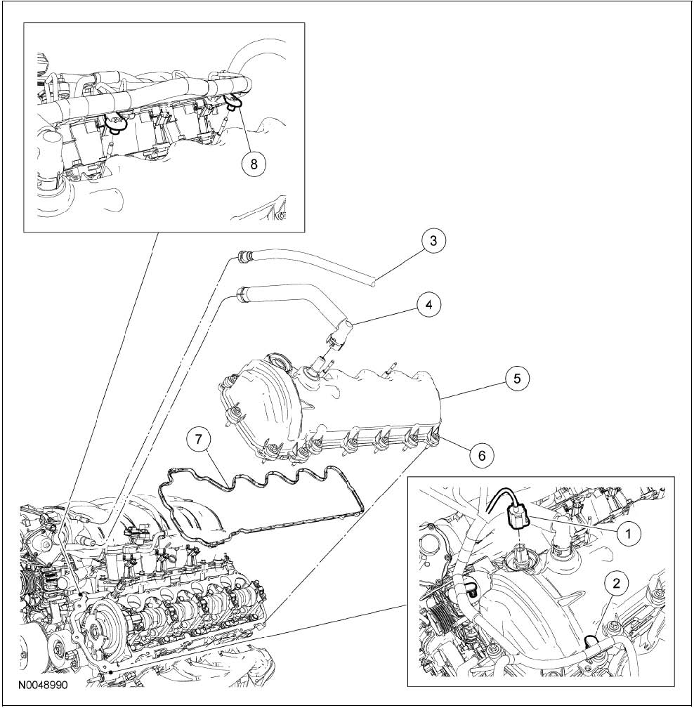
REMOVAL:
STEP 1: Remove the air cleaner assembly and outlet pipe. For additional information, refer to Section 303-12.
STEP 2: Remove the LH ignition coils. For additional information, refer to Section 303-07B.
STEP 3: Remove the oil level indicator and tube. For additional information, refer to Oil Level Indicator and Tube in this section.
STEP 4: Disconnect the evaporative emissions (EVAP) tube from the intake manifold.
STEP 5: Remove the PCV tube.
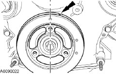
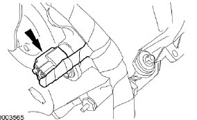
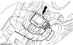
STEP 6: Disconnect the LH variable camshaft timing (VCT) solenoid electrical connector and detach the 2 wiring harness pin-type retainers.
STEP 7: Detach the 2 wiring harness retainers from the valve cover stud bolts.
STEP 8: CAUTION: Do not use metal scrapers, wire brushes, power abrasive discs or other abrasive means to clean the sealing surfaces. These tools cause scratches and gouges which make leak paths. Use a plastic scraping tool to remove all traces of old sealant.
Loosen the 15 fasteners and remove the LH valve cover and gasket.
- Clean the valve cover mating surface of the cylinder head with silicone gasket remover and metal surface prep. Follow the directions on the packaging.
- Discard the valve cover gasket. Clean the valve cover gasket groove with soap and water or a suitable solvent.
INSTALLATION:
STEP 1: NOTE: If the valve cover is not secured within 4 minutes, the sealant must be removed and the sealing area cleaned with metal surface prep. Failure to follow this procedure can cause future oil leakage.
Apply a bead of silicone gasket and sealant in 2 places where the engine front cover meets the cylinder head.
REMOVAL:
STEP 1: Remove the air cleaner assembly and outlet pipe. For additional information, refer to Section 303-12.
STEP 2: Remove the LH ignition coils. For additional information, refer to Section 303-07B.
STEP 3: Remove the oil level indicator and tube. For additional information, refer to Oil Level Indicator and Tube in this section.
STEP 4: Disconnect the evaporative emissions (EVAP) tube from the intake manifold.
STEP 5: Remove the PCV tube.
STEP 6: Disconnect the LH variable camshaft timing (VCT) solenoid electrical connector and detach the 2 wiring harness pin-type retainers.
STEP 7: Detach the 2 wiring harness retainers from the valve cover stud bolts.
STEP 8: CAUTION: Do not use metal scrapers, wire brushes, power abrasive discs or other abrasive means to clean the sealing surfaces. These tools cause scratches and gouges which make leak paths. Use a plastic scraping tool to remove all traces of old sealant.
Loosen the 15 fasteners and remove the LH valve cover and gasket.
- Clean the valve cover mating surface of the cylinder head with silicone gasket remover and metal surface prep. Follow the directions on the packaging.
- Discard the valve cover gasket. Clean the valve cover gasket groove with soap and water or a suitable solvent.
INSTALLATION:
STEP 1: NOTE: If the valve cover is not secured within 4 minutes, the sealant must be removed and the sealing area cleaned with metal surface prep. Failure to follow this procedure can cause future oil leakage.
Apply a bead of silicone gasket and sealant in 2 places where the engine front cover meets the cylinder head.
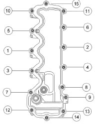
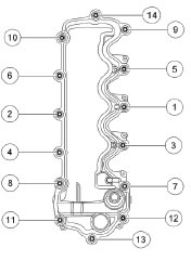
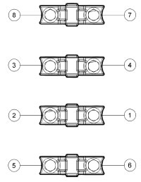
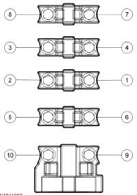
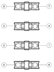
STEP 2: Position the LH valve cover and new gasket on the cylinder head and tighten the bolts in the sequence shown below. Tighten the valve cover bolts to 10 Nm (89 lb-in).
STEP 2: Position the LH valve cover and new gasket on the cylinder head and tighten the bolts in the sequence shown below. Tighten the valve cover bolts to 10 Nm (89 lb-in).
STEP 3: Attach the 2 wiring harness retainers to the valve cover stud bolts.
STEP 4: Connect the LH VCT solenoid electrical connector and attach the 2 wiring harness pin-type retainers.
STEP 5: Install the PCV tube.
STEP 6: Connect the EVAP tube to the intake manifold.
STEP 7: Install the oil level indicator and tube. For additional information, refer to Oil Level Indicator and Tube in this section.
STEP 8: Install the LH ignition coils. For additional information, refer to Section 303-07B.
STEP 9: Install the air cleaner assembly and outlet pipe. For additional information, refer to Section 303-12.
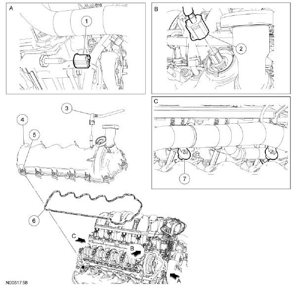
REMOVAL:
STEP 1: Remove the RH ignition coils. For additional information, refer to Section 303-07B.
STEP 2: Detach the wiring harness retainer from the engine front cover stud bolt.
STEP 3: Disconnect the RH variable camshaft timing (VCT) solenoid electrical connector.
STEP 4: Disconnect the PCV tube from the RH valve cover.
STEP 5: Detach the 3 wiring harness retainers from the valve cover stud bolts.
STEP 6: CAUTION: Do not use metal scrapers, wire brushes, power abrasive discs or other abrasive means to clean the sealing surfaces. These tools cause scratches and gouges which make leak paths. Use a plastic scraping tool to remove all traces of old sealant. Loosen the 14 fasteners and remove the RH valve cover and gasket.
- Clean the valve cover mating surface of the cylinder head with silicone gasket remover and metal surface prep. Follow the directions on the packaging.
- Discard the valve cover gasket. Clean the valve cover gasket groove with soap and water or a suitable solvent.
INSTALLATION:
STEP 1: NOTE: If the valve cover is not secured within 4 minutes, the sealant must be removed and the sealing area cleaned with metal surface prep. Failure to follow this procedure can cause future oil leakage.
Apply a bead of silicone gasket and sealant in 2 places where the engine front cover meets the cylinder head.
STEP 2: Position the RH valve cover and new gasket on the cylinder head and tighten the bolts in the sequence shown below. Tighten the valve cover bolts to 10 Nm (89 lb-in).
STEP 2: Position the RH valve cover and new gasket on the cylinder head and tighten the bolts in the sequence shown below. Tighten the valve cover bolts to 10 Nm (89 lb-in).
STEP 3: Attach the 4 wiring harness retainers to the valve cover stud bolts.
STEP 4: Connect the PCV tube to the RH valve cover.
STEP 5: Connect the RH VCT solenoid electrical connector.
STEP 6: Attach the wiring harness retainer to the engine front cover stud bolt.
STEP 7: Install the RH ignition coils. For additional information, refer to Section 303-07B.
REMOVAL:
CAUTION: The camshaft procedure must be followed exactly or damage to the valves and pistons will result.
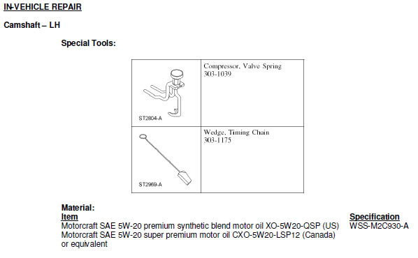
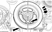
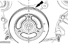
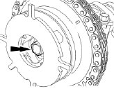
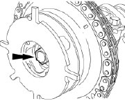
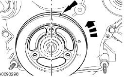
STEP 1: Position the crankshaft damper spoke at the 12 o’clock position and the timing mark indentation at the 1 o’clock position.
REMOVAL:
CAUTION: The camshaft procedure must be followed exactly or damage to the valves and pistons will result.
STEP 1: Position the crankshaft damper spoke at the 12 o’clock position and the timing mark indentation at the 1 o’clock position.
STEP 2: Remove the LH valve cover. For additional information, refer to Valve Cover – LH in this section.
STEP 3: CAUTION: Damage to the camshaft phaser and sprocket assembly will occur if mishandled or used as a lifting or leveraging device.
Loosen and back off the LH camshaft phaser and sprocket bolt one full turn.
STEP 4: Disconnect the LH camshaft position (CMP) sensor electrical connector
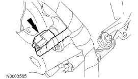
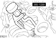
STEP 5: Remove the LH CMP sensor and the bolt.
STEP 5: Remove the LH CMP sensor and the bolt.
STEP 6: NOTE: If the camshaft lobes are not exactly positioned as shown, the crankshaft keyway will require one full additional rotation to 12 o’clock.
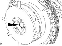
The No. 5 cylinder camshaft lobe must be coming up on the exhaust stroke. Verify by noting the position of the 2 intake camshaft lobes and the exhaust lobe on the No. 5 cylinder.
STEP 6: NOTE: If the camshaft lobes are not exactly positioned as shown, the crankshaft keyway will require one full additional rotation to 12 o’clock.
The No. 5 cylinder camshaft lobe must be coming up on the exhaust stroke. Verify by noting the position of the 2 intake camshaft lobes and the exhaust lobe on the No. 5 cylinder.
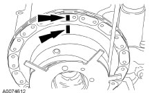
STEP 7: Remove only the 3 camshaft roller followers shown in the illustration below.
STEP 7: Remove only the 3 camshaft roller followers shown in the illustration below.
STEP 8: CAUTION: The camshaft roller followers must be installed in their original locations. Record camshaft roller follower locations. Failure to follow these instructions may result in engine damage.
NOTE: Do not allow the valve keepers to fall off the valve or the valve may drop into the cylinder. If a valve drops into the cylinder, the cylinder head must be removed. For additional information, refer to Cylinder Head in this section.
NOTE: It may be necessary to push the valve down while compressing the spring. Using the special tool, remove only the 3 designated camshaft roller followers from the previous step.
STEP 9: CAUTION: The crankshaft cannot be moved past the 6 o’clock position once set or engine damage may occur.
Rotate the crankshaft clockwise, as viewed from the front, positioning the crankshaft damper spoke at the 6 o’clock position and the timing mark indentation at the 7 o’clock position.
STEP 9: CAUTION: The crankshaft cannot be moved past the 6 o’clock position once set or engine damage may occur.
Rotate the crankshaft clockwise, as viewed from the front, positioning the crankshaft damper spoke at the 6 o’clock position and the timing mark indentation at the 7 o’clock position.
STEP 10: CAUTION: Engine is not freewheeling. Camshaft procedure must be followed exactly or damage to valves and pistons will result.
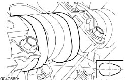
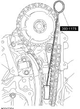
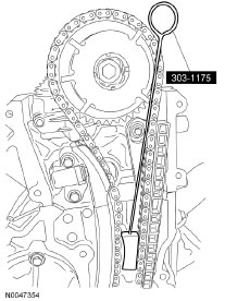
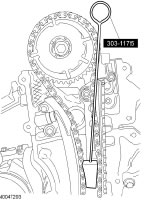
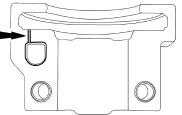
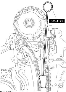
NOTE: The timing chain wedge tool must be installed square to the timing chain and the engine block.
NOTE: Engine front cover removed for clarity.
Install the special tool in the LH timing chain as shown in the illustration below.
STEP 10: CAUTION: Engine is not freewheeling. Camshaft procedure must be followed exactly or damage to valves and pistons will result.
NOTE: The timing chain wedge tool must be installed square to the timing chain and the engine block.
NOTE: Engine front cover removed for clarity.
Install the special tool in the LH timing chain as shown in the illustration below.
STEP 11: CAUTION: Do not remove the timing chain wedge tool at any time during assembly. If the special tool is removed or out of placement, the engine front cover must be removed and the engine must be re-timed. For additional information, refer to Timing Drive Components in this section.
CAUTION: The timing chain must be installed in its original position onto the camshaft phaser and sprocket using the scribed marks, or damage to valves and pistons will result.
NOTE: RH shown, LH similar
Scribe a location mark on the timing chain and the camshaft phaser and sprocket assembly.
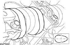
STEP 12: CAUTION: Remove the front thrust camshaft bearing cap straight upward from the bearing towers or the bearing cap may be damaged from side loading.
Remove the 2 bolts and the LH cylinder head camshaft front bearing cap.
STEP 12: CAUTION: Remove the front thrust camshaft bearing cap straight upward from the bearing towers or the bearing cap may be damaged from side loading.
Remove the 2 bolts and the LH cylinder head camshaft front bearing cap.
STEP 13: CAUTION: The camshaft bearing caps must be installed in their original locations. Record camshaft bearing cap locations. Failure to follow these instructions may result in engine damage.
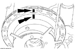
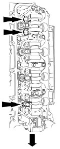
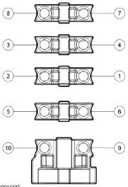
Remove the remaining bolts in the sequence shown below and remove the LH cylinder head camshaft bearing caps.
STEP 13: CAUTION: The camshaft bearing caps must be installed in their original locations. Record camshaft bearing cap locations. Failure to follow these instructions may result in engine damage.
Remove the remaining bolts in the sequence shown below and remove the LH cylinder head camshaft bearing caps.
STEP 14: Clean and inspect the LH camshaft bearing caps.
- The camshaft front thrust bearing cap contains an oil metering groove. Make sure the groove is free of foreign material.
STEP 14: Clean and inspect the LH camshaft bearing caps.
- The camshaft front thrust bearing cap contains an oil metering groove. Make sure the groove is free of foreign material.
STEP 15: CAUTION: Damage to the camshaft phaser and sprocket assembly will occur if mishandled or used as a lifting or leveraging device.
CAUTION: Only use hand tools to remove the camshaft phaser and sprocket bolt or damage may occur to the camshaft or camshaft phaser and sprocket.
CAUTION: Do not remove the timing chain wedge tool at any time during assembly. If the special tool is removed or out of placement, the engine front cover must be removed and the engine must be re-timed. For additional information, refer to Timing Drive Components in this section.
Remove the bolt and withdraw the camshaft from the camshaft phaser and sprocket assembly, leaving the camshaft phaser and sprocket assembly in place.
- Discard the bolt and washer.
STEP 16: Inspect the camshaft phaser and sprocket for damage. For additional information, refer to Camshaft Phaser and Sprocket in this section.
INSTALLATION:
STEP 1: Lubricate the camshaft and camshaft journals with clean engine oil.
STEP 2: CAUTION: Do not remove the timing chain wedge tool at any time during assembly. If the special tool is removed or out of placement, the engine front cover must be removed and the engine must be re-timed. For additional information, refer to Timing Drive Components in this section.
CAUTION: Damage to the camshaft phaser and sprocket assembly will occur if mishandled or used as a lifting or leveraging device.
NOTE: Do not allow the camshaft roller followers to move out of position when installing the camshaft.
Install the camshaft into the camshaft phaser and sprocket assembly and onto the head. Install a new camshaft phaser and sprocket bolt finger-tight.

STEP 3: CAUTION: Do not remove the timing chain wedge tool at any time during assembly. If the special tool is removed or out of placement, the engine front cover must be removed and the engine must be re-timed. For additional information, refer to Timing Drive Components in this section.
CAUTION: The timing chain must be installed in its original position onto the camshaft phaser and sprocket using the scribed marks, or damage to valves and pistons will result. NOTE: RH shown, LH similar
Verify the camshaft phaser and sprocket and timing chain scribe marks are still in alignment.
STEP 4: NOTE: Do not allow the camshaft roller followers to move out of position when installing the camshaft. Install the camshaft bearing caps in their original locations.
- Lubricate the camshaft bearing caps with clean engine oil.
- Position the front camshaft bearing cap.
- Position the remaining camshaft bearing caps.
- Install the bolts loosely.
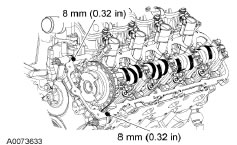
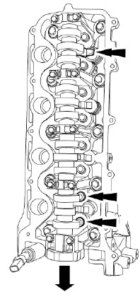
STEP 5: Tighten the bolts in the sequence shown below. Tighten to 10 Nm (89 lb-in).
STEP 4: NOTE: Do not allow the camshaft roller followers to move out of position when installing the camshaft. Install the camshaft bearing caps in their original locations.
- Lubricate the camshaft bearing caps with clean engine oil.
- Position the front camshaft bearing cap.
- Position the remaining camshaft bearing caps.
- Install the bolts loosely.
STEP 5: Tighten the bolts in the sequence shown below. Tighten to 10 Nm (89 lb-in).
STEP 6: NOTE: Engine front cover removed for clarity.
Remove the special tools.
STEP 6: NOTE: Engine front cover removed for clarity.
Remove the special tools.
STEP 7: Rotate the crankshaft a half turn counterclockwise and position the crankshaft damper spoke at the 12 o’clock position and the timing mark indentation at the 1 o’clock position.
STEP 7: Rotate the crankshaft a half turn counterclockwise and position the crankshaft damper spoke at the 12 o’clock position and the timing mark indentation at the 1 o’clock position.
STEP 8: Verify correct camshaft position by noting the position of the No. 5 cylinder intake and exhaust camshaft lobes.
STEP 8: Verify correct camshaft position by noting the position of the No. 5 cylinder intake and exhaust camshaft lobes.
STEP 9: NOTE: Do not allow the valve keepers to fall off of the valve or the valve may drop into the cylinder. If a valve drops into a cylinder, the cylinder head must be removed. For additional information, refer to Cylinder Head in this section.
NOTE: It may be necessary to push the valve down while compressing the spring. Using the special tool, install the 3 originally removed camshaft roller followers.
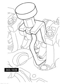
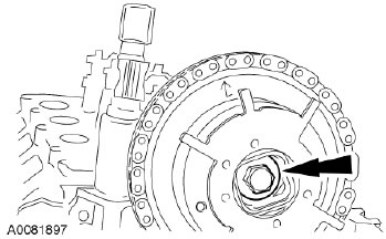
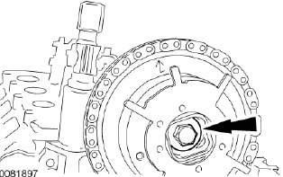
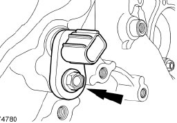
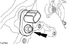
STEP 10: Install the CMP sensor and the bolt.
STEP 10: Install the CMP sensor and the bolt.

STEP 11: Connect the CMP electrical connector.
STEP 11: Connect the CMP electrical connector.
STEP 12: CAUTION: Only use hand tools to install the camshaft phaser and sprocket assembly or damage may occur to the camshaft or camshaft phaser and sprocket.
CAUTION: Damage to the camshaft phaser and sprocket assembly will occur if mishandled or used as a lifting or leveraging device.
Tighten the camshaft phaser and sprocket bolt in 2 stages.
- Stage 1: Tighten to 40 Nm (30 lb-ft).
- Stage 2: Tighten an additional 90 degrees.
STEP 13: Install the LH valve cover. For additional information, refer to Valve Cover – LH in this section.
STEP 13: Install the LH valve cover. For additional information, refer to Valve Cover – LH in this section.

REMOVAL:
CAUTION: The camshaft procedure must be followed exactly or damage to the valves and pistons will result.
STEP 1: Position the crankshaft damper spoke at the 12 o’clock position and the timing mark indentation at the 1 o’clock position.
REMOVAL:
CAUTION: The camshaft procedure must be followed exactly or damage to the valves and pistons will result.
STEP 1: Position the crankshaft damper spoke at the 12 o’clock position and the timing mark indentation at the 1 o’clock position.
STEP 2: Remove the RH valve cover. For additional information, refer to Valve Cover – RH in this section.
STEP 3: CAUTION: Damage to the camshaft phaser and sprocket assembly will occur if mishandled or used as a lifting or leveraging device. Loosen and back off the RH camshaft phaser and sprocket bolt one full turn.
STEP 4: Disconnect the RH camshaft position (CMP) sensor electrical connector.
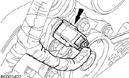
STEP 5: Remove the bolt and the RH CMP sensor.
STEP 5: Remove the bolt and the RH CMP sensor.
STEP 6: NOTE: If the camshaft lobes are not exactly positioned as shown, the crankshaft will require one full additional rotation to 12 o’clock.
The No. 1 cylinder camshaft lobe must be coming up on the exhaust stroke. Verify by noting the position of the 2 intake camshaft lobes and the exhaust lobe on the No. 1 cylinder.
STEP 7: Remove only the 3 camshaft roller followers shown in the illustration below.
STEP 7: Remove only the 3 camshaft roller followers shown in the illustration below.
STEP 8: CAUTION: The camshaft roller followers must be installed in their original locations. Record camshaft roller follower locations. Failure to follow these instructions may result in engine damage.
NOTE: Do not allow the valve keepers to fall off the valve or the valve may drop into the cylinder. If a valve drops into the cylinder, the cylinder head must be removed. For additional information, refer to Cylinder Head in this section.
NOTE: It may be necessary to push the valve down while compressing the spring. Using the special tool, remove only the 3 designated camshaft roller followers from the previous step.
STEP 9: CAUTION: The crankshaft cannot be moved past the 6 o’clock position once set or engine damage may occur.
Rotate the crankshaft clockwise, as viewed from the front, positioning the crankshaft damper spoke at the 6 o’clock position and the timing mark indentation at the 7 o’clock position.
STEP 9: CAUTION: The crankshaft cannot be moved past the 6 o’clock position once set or engine damage may occur.
Rotate the crankshaft clockwise, as viewed from the front, positioning the crankshaft damper spoke at the 6 o’clock position and the timing mark indentation at the 7 o’clock position.
STEP 10: CAUTION: Engine is not freewheeling. Camshaft procedure must be followed exactly or damage to valves and pistons will result.
NOTE: The timing chain wedge tool must be installed square to the timing chain and the engine block.
NOTE: Engine front cover removed for clarity.
Install the special tool in the RH timing chain as shown in the illustration below.
STEP 11: CAUTION: Do not remove the timing chain wedge tool at any time during assembly. If the special tool is removed or out of placement, the engine front cover must be removed and the engine must be re-timed. For additional information, refer to Timing Drive Components in this section.
CAUTION: The timing chain must be installed in its original position onto the camshaft phaser and sprocket using the scribed marks, or damage to valves and pistons will result. Scribe a location mark on the timing chain and the camshaft phaser and sprocket assembly.
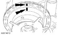
STEP 12: CAUTION: Remove the front thrust camshaft bearing cap straight upward from the bearing towers or the bearing cap may be damaged from side loading.
Remove the 2 bolts and the RH cylinder head camshaft front bearing cap.
STEP 12: CAUTION: Remove the front thrust camshaft bearing cap straight upward from the bearing towers or the bearing cap may be damaged from side loading.
Remove the 2 bolts and the RH cylinder head camshaft front bearing cap.
STEP 13: CAUTION: The camshaft bearing caps must be installed in their original locations. Record camshaft bearing cap locations. Failure to follow these instructions may result in engine damage.
Remove the remaining bolts in the sequence shown and remove the RH cylinder head camshaft bearing caps.
STEP 13: CAUTION: The camshaft bearing caps must be installed in their original locations. Record camshaft bearing cap locations. Failure to follow these instructions may result in engine damage.
Remove the remaining bolts in the sequence shown and remove the RH cylinder head camshaft bearing caps.
STEP 14: Clean and inspect the RH camshaft bearing caps.
- The camshaft front thrust bearing cap contains an oil metering groove. Make sure the groove is free of foreign material.
STEP 14: Clean and inspect the RH camshaft bearing caps.
- The camshaft front thrust bearing cap contains an oil metering groove. Make sure the groove is free of foreign material.
STEP 15: CAUTION: Damage to the camshaft phaser and sprocket assembly will occur if mishandled or used as a lifting or leveraging device.
CAUTION: Only use hand tools to remove the camshaft phaser and sprocket bolt or damage may occur to the camshaft or camshaft phaser and sprocket.
CAUTION: Do not remove the timing chain wedge tool at any time during assembly. If the special tool is removed or out of placement, the engine front cover must be removed and the engine must be re-timed. For additional information, refer to Timing Drive Components in this section.
Remove the bolt and withdraw the camshaft from the camshaft phaser and sprocket assembly, leaving the camshaft phaser and sprocket assembly in place.
- Discard the bolt and washer.
STEP 16: Inspect the camshaft phaser and sprocket for damage. For additional information, refer to Camshaft Phaser and Sprocket in this section.
INSTALLATION:
STEP 1: Lubricate the camshaft and camshaft journals with clean engine oil.
STEP 2: CAUTION: Do not remove the timing chain wedge tool at any time during assembly. If the special tool is removed or out of placement, the engine front cover must be removed and the engine must be re-timed. For additional information, refer to Timing Drive Components in this section.
CAUTION: Damage to the camshaft phaser and sprocket assembly will occur if mishandled or used as a lifting or leveraging device.
NOTE: Do not allow the camshaft roller followers to move out of position when installing the camshaft.
Install the camshaft into the camshaft phaser and sprocket assembly and onto the head. Install a new camshaft phaser and sprocket bolt finger-tight.
STEP 3: CAUTION: Do not remove the timing chain wedge tool at any time during assembly. If the special tool is removed or out of placement, the engine front cover must be removed and the engine must be re-timed. For additional information, refer to Timing Drive Components in this section.
CAUTION: The timing chain must be installed in its original position onto the camshaft phaser and sprocket using the scribed marks, or damage to valves and pistons will result. Verify the camshaft phaser and sprocket and timing chain scribe marks are still in alignment.
STEP 4: NOTE: Do not allow the camshaft roller followers to move out of position when installing the camshaft.
Install the camshaft bearing caps in their original locations.
- Lubricate the camshaft bearing caps with clean engine oil.
- Position the front camshaft bearing cap.
- Position the remaining camshaft bearing caps.
- Install the bolts loosely.
STEP 5: Tighten the bolts in the sequence shown below. Tighten to 10 Nm (89 lb-in)
STEP 6: NOTE: Engine front cover removed for clarity. Remove the special tool.
STEP 6: NOTE: Engine front cover removed for clarity. Remove the special tool.
STEP 7: Rotate the crankshaft a half turn counterclockwise and position the crankshaft damper spoke at the 12 o’clock position and the timing mark indentation at the 1 o’clock position.
STEP 7: Rotate the crankshaft a half turn counterclockwise and position the crankshaft damper spoke at the 12 o’clock position and the timing mark indentation at the 1 o’clock position.
STEP 8: Verify correct camshaft position by noting the position of the No. 1 cylinder intake and exhaust camshaft lobes.
STEP 8: Verify correct camshaft position by noting the position of the No. 1 cylinder intake and exhaust camshaft lobes.
STEP 9: NOTE: Do not allow the valve keepers to fall off of the valve or the valve may drop into the cylinder. If a valve drops into a cylinder, the cylinder head must be removed. For additional information, refer to Cylinder Head in this section.
NOTE: It may be necessary to push the valve down while compressing the spring. Using the special tool, install the 3 originally removed camshaft roller followers.
STEP 10: Install the CMP sensor and the bolt. Tighten bolt to 10 Nm (89 lb-in).
STEP 10: Install the CMP sensor and the bolt. Tighten bolt to 10 Nm (89 lb-in).
STEP 11: Connect the CMP electrical connector.
STEP 11: Connect the CMP electrical connector.
STEP 12: CAUTION: Only use hand tools to install the camshaft phaser and sprocket assembly or damage may occur to the camshaft or camshaft phaser and sprocket.
CAUTION: Damage to the camshaft phaser and sprocket assembly will occur if mishandled or used as a lifting or leveraging device.
Tighten the new camshaft phaser and sprocket bolt in 2 stages.
- Stage 1: Tighten to 40 Nm (30 lb-ft).
- Stage 2: Tighten an additional 90 degrees.
STEP 13: Install the RH valve cover. For additional information, refer to Valve Cover – RH in this section.
STEP 13: Install the RH valve cover. For additional information, refer to Valve Cover – RH in this section.