Best Sellers
How to Install Ford Racing GT350R Leather & Alcantara Steering Wheel Kit w/ Bezels on your Musta
Steering Wheel Removal
NOTICE: To prevent damage to the clockspring, make sure the front wheels are in the straight-ahead position.
NOTE: Removal steps in this procedure may contain installation details.
NOTE: LHD shown, RHP similar.
1. Remove the driver airbag module.
Driver Airbag Removal
WARNING: The following procedure prescribes critical repair steps required for correct restraint system operation during a crash. Follow all notes and steps carefully. Failure to follow step instructions may result in incorrect operation of the restraint system and increases the risk of serious personal injury or death in a crash.
la.Depower the SRS.
Depower SRS
WARNING: Incorrect repair techniques or actions can cause an accidental Supplemental Restraint System (SRS) deployment. Never compromise or depart from these instructions. Failure to precisely follow all instructions could result in serious personal injury from an accidental deployment.
Pyrotechnic Device Health and Safety Precautions
WARNING: Always carry a live airbag with the deployment door, trim cover or tear seam pointed away from the body. Do not place a live airbag down with the deployment door, trim cover or tear seam facing down. Failure to follow these instructions may result in serious personal injury in the event of an accidental deployment.
WARNING: Always carry or transport a live safety belt inflator with the safety belt buckle bolt installed in the inflator tube hand tight. Failure to follow this instruction may result in serious personal injury in the event of an accidental deployment.
WARNING: Deploy all supplemental restraint system (SRS) devices (air bags, pre-tensioners, load limiters, etc.) outdoors with all personnel at least 9 meters (30 feet) away to make sure of personal safety. Due to the loud report which occurs when an SRS device is deployed, hearing protection is required. Failure to follow these instructions may result in serious personal injury.
WARNING: Do not bleach or re-dye the safety belt webbing, as the webbing may weaken. Failure to follow this instruction may increase the risk of serious personal injury or death in a crash.
WARNING: If a vehicle has been in a crash, inspect the restraints control module (RCM) and the impact sensor (if equipped) mounting areas for deformation. If damaged, restore the mounting areas to the original production configuration. A new RCM and sensors must be installed whether or not the airbags have deployed. Failure to follow these instructions may result in serious personal injury or death in a crash.
WARNING: All safety belt components must be inspected and corrected as part of any collision repair. Inspect all safety belt components as prescribed by Safety Belt Inspection and Repair After a Collision found in Section 501-20A General Procedures of this manual. Failure to follow this instruction may result in incorrect operation of the safety belt system and increase the risk of serious personal injury or death in a crash.
WARNING: Anytime the Safety Canopy or side air curtain has deployed, a new headliner and new roof pillar upper trim panels with attaching hardware must be installed. Make sure the headliner includes the word AIRBAG where it meets each roof B-pillar trim panel. Remove any other damaged components or hardware and replace with new. Always use new torque-prevailing type J-nuts when installing the Safety Canopy. Failure to follow these instructions may result in the Safety Canopy or side air curtain deploying incorrectly and increases the risk of serious personal injury or death in a crash.
WARNING: Do not repair or service restraint component connector terminals. If restraint connector terminals need repair, replace with the service connector pigtails. Failure to follow this instruction may result in incorrect operation of the vehicle safety restraint, which increases the risk of serious personal injury or death in a crash.
WARNING: Never disassemble or tamper with seat belt deployable components, including pre-tensioners, load limiters and inflators. Never back probe deployable device electrical connectors. Tampering or back probing may cause an accidental deployment and result in personal injury or death.
WARNING: Never tamper with, repair, or modify a Restraints Control Module (RCM) or any other Supplemental Restraint System (SRS) component. Failure to follow this instruction may result in incorrect operation of the Supplemental Restraint System (SRS), which increases the risk of serious personal injury or death in a crash.
WARNING: Never probe the electrical connectors on airbag, Safety Canopy or side air curtain assemblies. Failure to follow this instruction may result in the accidental deployment of these assemblies, which increases the risk of serious personal injury or death.
WARNING: Do not handle, move or change the original horizontal mounting position of the restraints control module (RCM) while the RCM is connected and the ignition switch is ON. Failure to follow this instruction may result in the accidental deployment of the Safety Canopy and cause serious personal injury or death.
WARNING: Do not obstruct or place objects in the deployment path of the Safety Canopy or side air curtain assembly. Never insert any type of fastener or tie strap around any portion of the Safety Canopy, side air curtain assembly, or related interior trim panel. Failure to follow this instruction may result in the Safety Canopy or side airbag curtain deploying incorrectly and increases the risk of serious personal injury or death in a crash.
WARNING: Occupant Classification System (OCS) parts are calibrated as an assembly and must only be replaced in the configuration they are sold. Never separate parts of an assembly. Failure to follow this instruction may result in incorrect operation of the OCS and increases the risk of serious personal injury or death in a crash.
WARNING: Never allow oil, grease, water or foreign contaminants to get on/in the occupant classification system (OCS) components or electrical connectors. Failure to follow this instruction may result in incorrect operation of the OCS and increases the risk of serious personal injury or death in a crash.
WARNING: Always tighten the fasteners of the restraints control module (RCM) and impact sensor (if equipped) to the specified torque. Failure to do so may result in incorrect restraint system operation, which increases the risk of personal injury or death in a crash.
WARNING: Always carry a live Safety Canopy or side air curtain assembly with the tear seam pointed away from your body. Failure to follow this instruction may result in serious personal injury or death in the event of an accidental deployment.
WARNING: Do not paint any airbag trim covers or deployment doors. Paint may cause the airbag to deploy incorrectly. Failure to follow this instruction may increase the risk of serious personal injury or death in a crash.
WARNING: Always carry the live hood actuator by holding it around the cylinder with the mounting bracket up and with the cap pointing away from the body. Always place the live hood actuator on its side with the cap pointing away from people. Never place anything in front of the cap. Failure to follow these instructions may result in serious personal injury in the event of an accidental deployment.
WARNING: If a vehicle has been in a pedestrian impact, inspect the impact sensor mounting areas for damage. If damaged, a new bumper cover must be installed. New pedestrian impact sensors must be installed. Failure to follow these instructions may result in serious personal injury or death in a pedestrian impact.
WARNING: Do not repair or service pedestrian protection system component connector terminals. If pedestrian protection system connector terminals need repair, replace with the service connector pigtails. Failure to follow this instruction may result in incorrect operation of the vehicle pedestrian protection system, which increases the risk of serious personal injury or death in a pedestrian impact.
WARNING: Never tamper with, repair, or modify a pedestrian protection system component. Failure to follow this instruction may result in incorrect operation of the pedestrian protection system, which increases the risk of serious personal injury or death in a pedestrian impact.
WARNING: Never probe the electrical connectors on pedestrian protection system pyrotechnic assemblies. Failure to follow this instruction may result in the accidental deployment of these assemblies, which increases the risk of serious personal injury or death.
WARNING: Pyrotechnic components are very hot immediately after deployment and might be covered with pyrotechnic residuals. Do not handle pyrotechnic components immediately after deployment. Always wear protective gloves, safety glasses and breathing protection to prevent skin contact and inhaling of pyrotechnic residuals. Failure to follow this instruction may result in serious personnel injury.
1 b. Determine if a SRS fault is present. Turn the ignition OFF and wait 10 seconds, then turn the ignition ON and monitor the airbag warning indicator. The airbag warning indicator illuminates continuously for approximately 6 seconds and then turns off. Continue to monitor the airbag warning indicator for approximately 30 seconds as this is the time required for the RCM to complete testing of the SRS.
2b.
• If a SRS fault is present the airbag warning indicator either fails to light, remains lit continuously or flashes.
The flashing may not occur until approximately 30 seconds after the ignition has been turned from OFF to ON. If this occurs, diagnose and repair any SRS faults before proceeding with other repairs.
• If after the ignition has been turned ON for 30 seconds the airbag warning indicator remains unlit with no
chime or SRS message displayed in the message center, no SRS fault is present.
• If the airbag warning indicator is inoperative and a SRS fault exists, a chime sounds in a pattern of 5 sets
of 5 beeps or a message displays in the message center. If this occurs, diagnose and repair the airbag warning indicator and any SRS faults before proceeding with other repairs.
No SRS Fault Present (with ignition ON, airbag warning indicator stays off after prove out)
3b. . WARNING: Turn the ignition OFF and wait one minute to deplete the backup power supply. Ignition must remain OFF until repair is complete. Failure to follow this instruction may result in serious personal injury or death in the event of an accidental deployment.
Turn the ignition OFF and wait one minute before continuing vehicle service.
4b. Turn the ignition OFF.
5b. Remove the RCM fuse.
6b. Turn the ignition ON.
7b. Using a diagnostic scan tool, carry out a Network Test. Verify that the RCM does not respond to the Network Test. If the RCM passes the Network Test, remove the correct RCM fuse and repeat the Network Test to verify before proceeding.
8b. Turn the ignition OFF.
9b. Disconnect the battery.
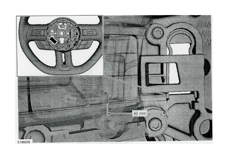
3a. NOTE: The driver airbag has been removed for clarity.
Angle the inserted end of the Allen key up and toward the front of the vehicle for ideal contact with the spring clip.
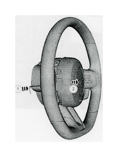
4a.
4-1. Push in on the steering wheel spring clip to release the driver airbag retainer. 4-2-Pull the LH side of driver airbag out and separate it from the steering wheel.
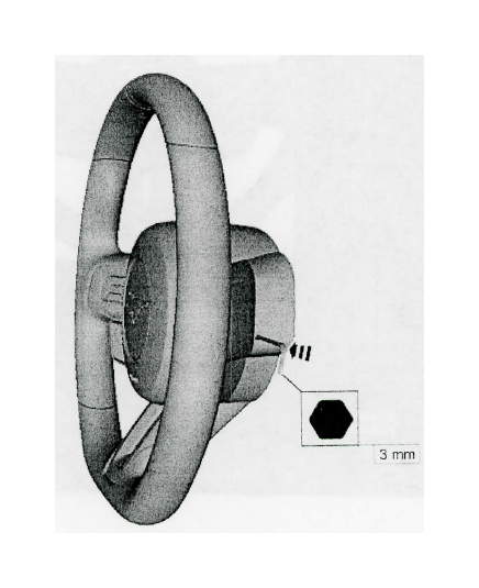
5a. At the RH side of the steering wheel cover, locate the hole and insert a 3 mm (0.125 inch) Allen key.
6a. NOTE: The driver airbag has been removed for clarity.
Angle the inserted end of the Allen key up and toward the front of the vehicle for ideal contact with the spring clip.
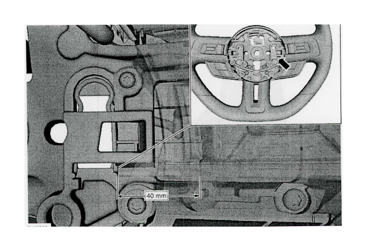
7a.
7-1. Push in on the steering wheel spring clip to release the driver airbag retainer. 7-2. Pull the driver airbag out and separate it from the steering wheel.
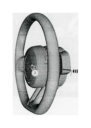
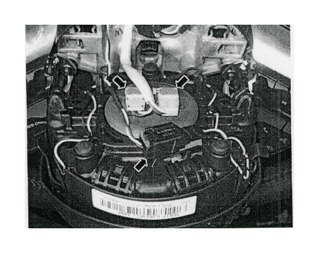
8a. Disconnect the 3 driver airbag electrical connectors.
2. (continued from page 1)
1. Disconnect the steering wheel switches electrical connector.
2. Remove the steering wheel bolt and the steering wheel. Torque: 35 Ib.ft (47.5 Nm)
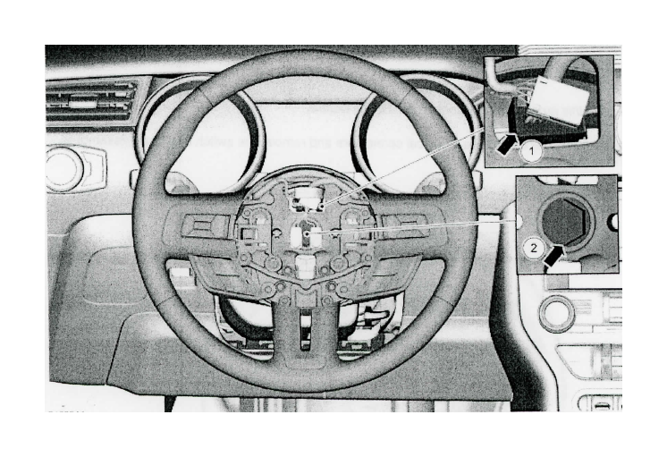
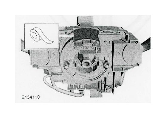
3. Tape the clock-spring rotor to the outer housing to keep it from rotating.
Steering Wheel Multifunction Switch
Removal
NOTE: Removal steps in this procedure may contain installation details.
1. Remove the retainers, disconnect the electrical connectors and remove the switch and bezel assemblies. Torque: 44 Ib.in (5 Nm)
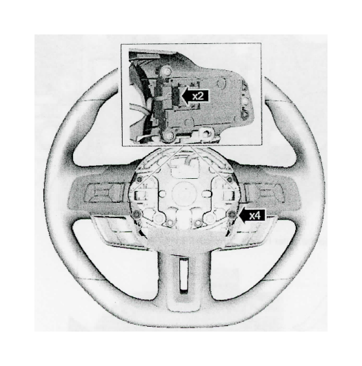
1. On both sides.
Remove the retainers and the upper steering wheel switch.
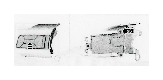
Lower steering wheel switch
1. Remove the retainers. Torque: 44 lb.in (5 Nm)
2. Disconnect the electrical connectors.
3. Remove the lower steering wheel switches.
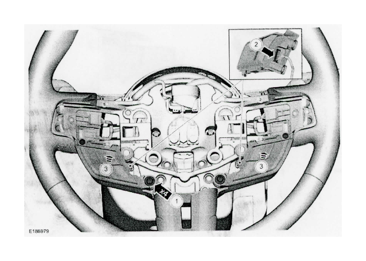
Installation Steering Wheel Multifunction Switch
1. To install, reverse the removal procedure.
Steering Wheel Installation
1. To install, reverse the removal procedure.
Install the steering wheel and bolt Torque: 35 Ib.ft (47.5 Nm)
Airbag Installation
WARNING: Incorrect repair techniques or actions can cause an accidental Supplemental Restraint System deployment. Make sure the restraint system is depowered before reconnecting the component. Refer to the Supplemental Restraint System depowering General Procedure in section 501-20B. Failure to precisely follow depowering instructions could result in serious personal injury from an accidental deployment.
1. Connect the 3 driver airbag electrical connectors.
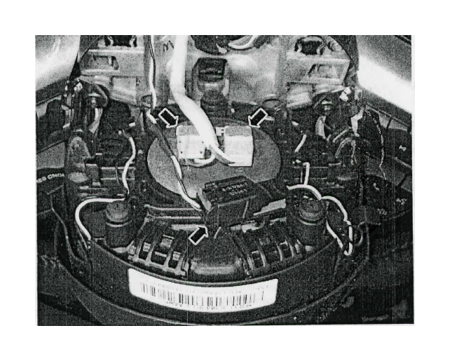
2. Align the driver airbag to the steering wheel and push in, engaging the driver airbag retainers to the spring clips.
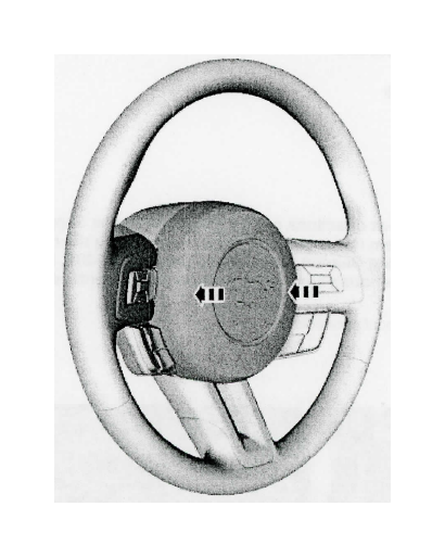
3. Repower the SRS.
No SRS Fault Present At Beginning of Repair
1. Prove out the SRS. Verify all airbags are installed and connected and the ignition is OFF. Wait 10 seconds then turn the ignition ON and monitor the airbag warning indicator. The airbag warning indicator illuminates continuously for approximately 6 seconds and turns off. Continue to monitor the airbag warning indicator for approximately 30 seconds as this is the time required for the RCM to complete testing of the SRS.
2.
• If a SRS fault is present, the airbag warning indicator either fails to light, remains lit continuously or flashes.
The flashing may not occur until approximately 30 seconds after the ignition has been turned from OFF to ON. If this occurs, diagnose and repair any SRS faults before proceeding with other repairs.
• If, after the ignition has been turned on for 30 seconds, the airbag warning indicator remains unlit with no
chime or SRS message displayed in the message center, no SRS fault is present.
• If the airbag warning indicator is inoperative and a SRS fault exists, a chime sounds in a pattern of 5 sets
of 5 beeps or a message displays in the message center. If this occurs, diagnose and repair the airbag warning indicator and any SRS faults before proceeding with other repairs.


