Best Sellers
How to Install Maximum Motorsports Cross-Axis Joint Replacement Kit (99-04 Cobra) on your Ford Mustang
Installation Time
1 days
Tools Required
- Ratchet
- Sockets (assorted)
- Torque Wrench
- Wrenches (assorted)
- Tie-Rod End Splitting Tool
- Large Flat-Blade Screwdriver or Pry Bar
- Small File or Sanding Wheel
- Snap-Ring Pliers (supplied)
- Joint Removal Tool (supplied)
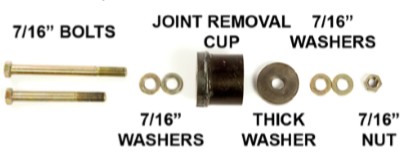
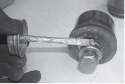
- Grease or Anti-Seize Compound
- Green Loctite (supplied)
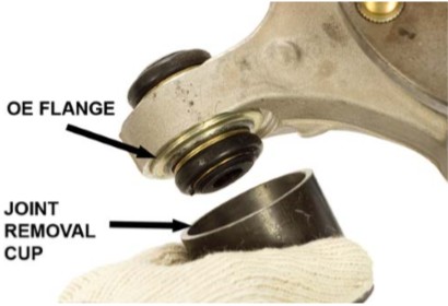
- Safety Glasses
Shop Parts in this Guide
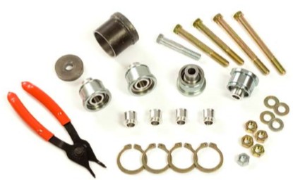
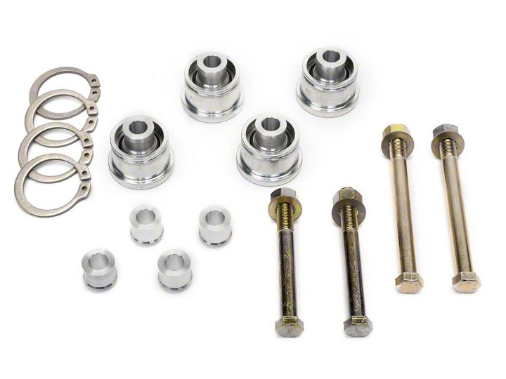
Thank you for purchasing the MMIRSB-3 IRS CrossAxis Replacement Joints. The IRS cross-axis joints are the pivots on the rear spindles where the rear control arms attach. Stock replacements for the joints are only available by purchasing a complete rear spindle assembly from your local Ford dealer. MM’s upgraded replacement for the plastic-bushed OEM joints utilizes a high-strength Teflon-lined spherical bearing. These bearings provide long service life, along with easier future maintenance. The MM kit includes tooling to aid in removing the OEM joints and installing the MM replacements.
This MMIRSB-3 kit fits 1999-2004 IRS equipped vehicles. One kit replaces all four cross-axis joints on one Mustang.
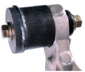
Read all instructions before beginning work. Following instructions in the proper sequence will ensure the best and easiest installation.
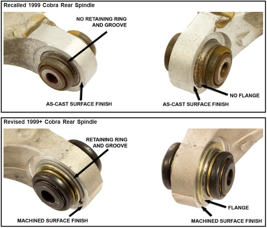
NOTE: Ford recalled the 1999 model year Mustang Cobra to replace the IRS rear spindles because of problems with the cross-axis joints. The MM kit does not fit the original 1999 spindles; only the spindles replaced in the recall, and the post-1999 OEM spindles. Reference the last page of these instructions for detailed pictures that illustrate the differences between the two spindles.
NOTE: Your MM Consumer Instructions show how to remove the IRS spindle completely from the car so that you may perform the job on a workbench for convenience. This installation can be completed
without removing the spindle from the vehicle; by swapping one bearing at a time by disconnecting the associated upper or lower control arm, and swinging it out of the way. It is your choice to decide which method is most convenient to you.
NOTE: If using a hydraulic press instead of the supplied installation tools, take care when pressing the bearings in and out of the spindles, as they can be easily damaged.
Vehicle Disassembly
1. Block the front wheels to prevent the car from rolling, then jack up the rear of the vehicle and place it safely on jack stands.
2. Remove the rear wheels.
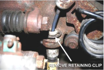
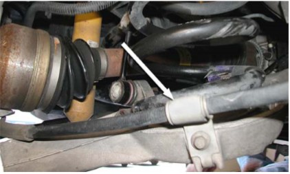
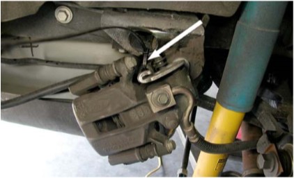
3. Make sure the parking brake cable is not set. Starting on one side of the vehicle, remove the parking brake cable housing retaining clip.
4. Disconnect the parking brake cable from the parking brake lever on the caliper, and remove the cable from the locating hole in the caliper.
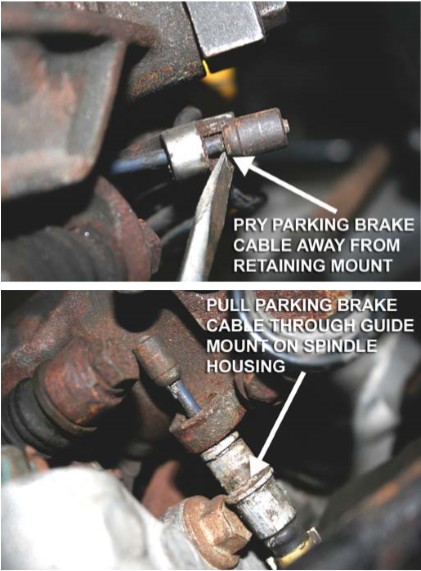
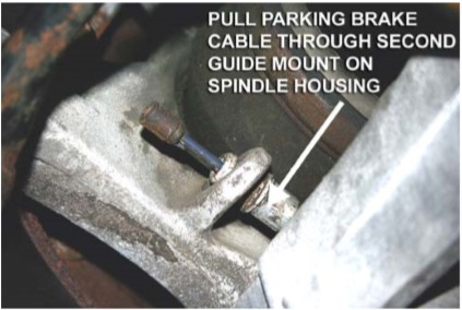
NOTE: It may be necessary to unbolt the cable from the lower control arm in order to pull the cable from the locating hole in the caliper.
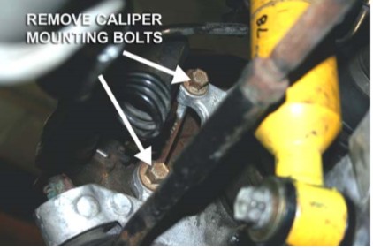
5. Remove the two bolts holding the caliper assembly to the spindle. Remove the caliper and hang it securely from the rear chassis mounting bracket for the IRS subframe. Do NOT let a caliper hang by the brake hose, as damage to the hose may result.
6. Remove the brake rotors.
7. Use a suitable tie-rod end splitting tool and separate the outer tie-rod end from the steering arm of the spindles. Avoid using a pickle fork as they can damage the rubber boot on the tie rod end. MM recommends using a ball joint separator tool.
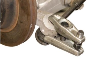
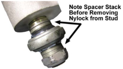
Note: If you have the MMIRSTR-1 or MMIRSTR-2 Adjustable IRS Tie-Rod Kit installed, it is not necessary to remove the tapered stud from the spindle. Simply unbolt the 5/8-18 Nylock Nut and remove the rod end from the tapered stud while taking note of the spacer stack arrangement for reinstallation purposes.
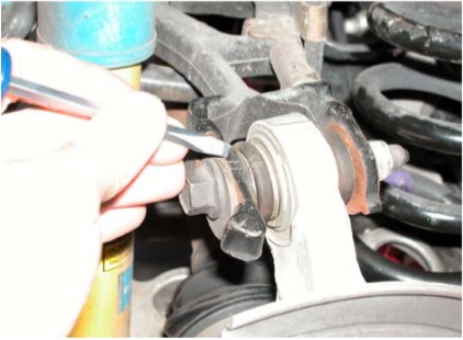
8. Use an awl or other sharp object to carefully mark the position of the eccentric camber adjustment bolt on the upper control arm. Aligning these marks during reassembly will help maintain the original camber setting.
9. Remove the mounting bolts securing the upper and lower control arms to the spindles.
10. Place a large flat-blade screwdriver or pry bar between the differential housing and axle halfshaft. Carefully pry the half-shaft out of the differential. Apply enough pressure to overcome the internal circlip.
NOTE: Take care to avoid damaging the axle seal and bearing surfaces.
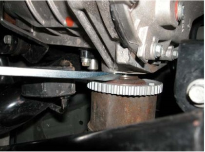
11. Pull the spindle/axle assembly out of the vehicle.
NOTE: If the vehicle will remain disassembled for a long period of time, we recommend sealing the holes for the axle shafts with tape to avoid contaminating the differential oil.
12. Repeat Steps 3-11 for the other side of the vehicle.
Cross-Axis Joint Removal
Please note that the half-shaft has been removed from the spindle in the following photos for illustrational purposes only. It is NOT necessary to remove the half-shaft for installation.
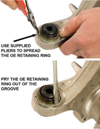
13. Remove the retaining rings holding the stock cross-axis joints in position. There is one ring on each cross-axis joint. Spread the retaining ring apart using the supplied snap ring pliers. Then, using a punch or awl, pry the retaining ring out of the groove.
NOTE: Wear Safety glasses! The retaining ring can be ejected at a high velocity during removal, potentially causing severe eye injury.
14. Coat both sides of the supplied Grade 8 washers and the threads of both bolts with grease or antiseize compound.
15. Place two of the washers under the head of the shorter supplied 7/16" bolt.
16. Place the Cross-Axis Joint Removal Cup on the flanged side of the OE cross axis joint. The edge of the Removal Cup should sit flush on the aluminum face.
17. Place the bolt through the Removal Cup and through the cross-axis joint.
18. Place the other two supplied washers on the end of the bolt.
19. Thread the supplied nut onto the bolt.
20. Using a pair of wrenches, tighten the bolt to pull the bearing into the Removal Cup.
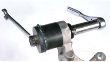
21. Repeat the process for the remaining cross-axis joints.
MM Cross-Axis Joint Installation
The following steps detail the installation of an MM Cross-Axis Joint. Under no circumstances should the Joint be installed by applying a load directly to its spherical bearing, as damage to the bearing will occur. For this reason, the Bearing Insert on the flanged side of the MM Cross-Axis Joint is not installed until after the Joint has been pressed into the spindle. All the necessary tooling is included to press the Joint in by properly applying the load to its bearing cup flange.
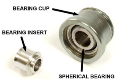
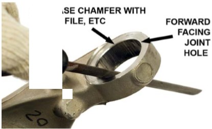
22. Using a small hand file or sanding drum, slightly increase the chamfer on the inside diameter of forward facing (towards the front of the car) cross-axis joint holes.
NOTE: The chamfer only needs to be large enough to allow the flanged face of the MM Cross-Axis Joint to rest flat against the spindle. If after installation a gap is visible between the flange and the spindle, the chamfer needs to be increased slightly.
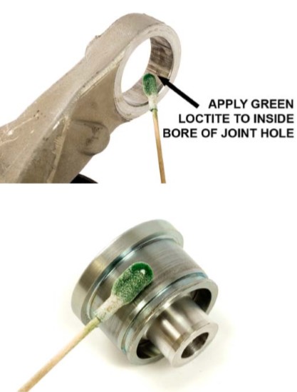
23. Apply a thin layer of the supplied Green Loctite to the inside diameter of the aluminum spindle’s cross-axis joint hole, and to the minor outside diameter of the MM Cross-Axis Joint. The surfaces must be wiped clean of any grease prior to the application of Loctite. Brake cleaner or Acetone is recommended, but any non-water based cleaner will work.
24. Slide one of the MM Cross-Axis Joints into an open cross-axis joint hole in the aluminum spindle until the groove on the outer diameter of the Assembly is no longer visible. The MM Cross-Axis Joint should be inserted from the front side of the spindle so that the flange on the Bearing Assembly is facing the front of the vehicle. The front of the aluminum spindle is the side opposite of where the brake caliper mounts.
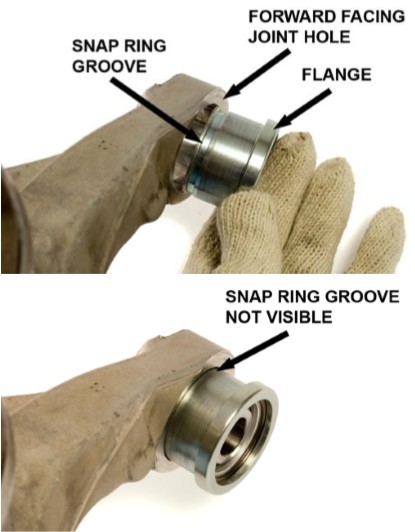
25. Place the Cross-Axis Joint Removal Cup on the corresponding rearward face of the spindle.
26. Place two greased washers under the head of the longer supplied 7/16" bolt and pass the bolt through the Removal Cup, and then through the MM Cross-Axis Joint. The end of the bolt should be facing the front of the vehicle.
27. Slide the Thick Installation Washer onto the bolt until it is resting against the flanged portion of the MM Cross-Axis Joint.
28. Place two greased washers and the nut on the end of the bolt. Reapply grease to the bolt threads if there is none left.
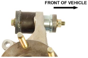
29. Using a pair of wrenches, draw the MM CrossAxis Joint into the aluminum spindle by tightening the bolt until it runs out of threads. Switch to the shorter bolt when this happens, and finish drawing the Joint into the spindle until the flanged portion is resting against the face of the spindle.
NOTE: Make sure that the MM Cross-Axis Joint goes in evenly. If it is crooked, damage to the IRS aluminum spindle will result.
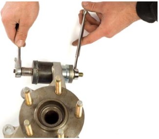
30. Remove the installation tool.
Orienting the Snap Rings
The snap rings supplied with the MMIRSB-3 kit have a flat face and a curved face due to the nature of their production. This curvature decreases the contact area between the snap ring and the retaining groove in the MM Cross-Axis Joint. Because of this, it is important to orient the curved face towards the spindle.
To identify the flat and curved face of the snap ring;
31. Place the supplied snap rings on a flat surface and view them from the side. When properly oriented, a small gap should be visible around the outer diameter of the ring and the surface. If no gap is visible, flip the snap rings over until a gap is visible. The snap ring face with the small gap is the curved face and conversely, the side without the gap is the flat face.
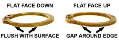
32. Using a felt marker or paint pen, mark the top, FLAT face of each snap ring.
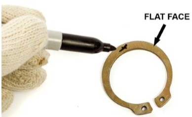
33. Using the supplied snap ring pliers, install the supplied snap ring into the groove on the MM Cross-Axis Joint, with the FLAT face of the snap ring facing AWAY from the spindle.
NOTE: The mark indicating the flat face made in the previous step should be visible after installation of the snap ring.
NOTE: Make sure that the snap ring is fully seated in the groove. When properly installed, the gap between the two ends of the snap ring should be less than ¼”.
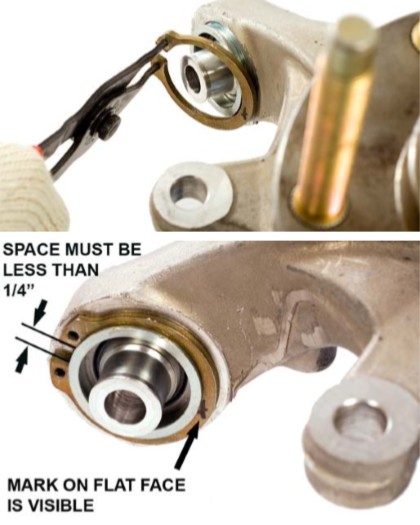
34. Repeat the process installing the three remaining MM Cross-Axis Joint. All four joints are oriented in the same direction; with the flange towards the front of the car.
Bearing Insert Installation
One Bearing Insert comes preinstalled in each MM Cross-Axis Joint. The remaining Bearing Inserts must be installed to complete the assembly. The following procedure uses the provided 7/16-14 x 2-3/4 bolt to install the Bearing Inserts, but a small hydraulic or arbor press could be used instead.
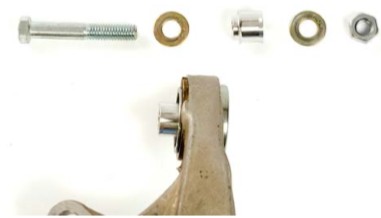
35. Place two greased washers under the 7/16-14 x 2-3/4 bolt head and pass the bolt through a preinstalled Bearing Insert.
36. Place one of the supplied Bearing Inserts onto the bolt so that the reduced diameter shoulder of the Insert is facing the bearing.
37. Place a washer and the provided 7/16-14 nut on the end of the bolt.
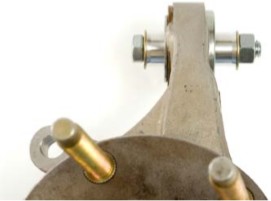
38. Draw the Bearing Insert into the spherical bearing by tightening the bolt with a pair of wrenches. Make sure the Insert seats flush against the face of the spherical bearing.
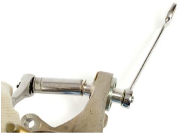
39. Repeat the process for the remaining Bearing Inserts.
Vehicle Reassembly
40. Slip the axles into the differential until the internal circlips snap into place.
41. Reconnect the upper and lower control arms, and the outer tie-rods. If using a MM Adjustable IRS Tie-Rod Kit, reinstall the spacer stack removed in Step 7.
42. Torque the mounting bolts to the following values: Upper Control Arm: 66 ft-lbs. Lower Control Arm: 85 ft-lb. Ball joint nut on Stock Outer Tie Rod: 35 ft-lbs. If using a MM Adjustable IRS Tie-Rod Kit, torque the 5/8-18 Nylock on the Tapered Stud to 65 ft-lbs.
NOTE: Use the alignment marks on the eccentric bolts made in Step 8 to set the camber.
43. Reinstall the brake rotors.
44. Reinstall the brake calipers. Torque the mounting bolts to 76 ft-lbs.
45. Reinstall the parking brake cables and retaining clips.
46. Install the rear wheels.
47. Lower the car safely to the ground. Torque the rear lug nuts to the manufacturer’s specifications.
48. Test-drive and enjoy! Recheck and re-torque all components after 1,000 miles.
The MMIRSB-3 IRS Cross-Axis Replacement Joints retain the stock geometry and do not require the vehicle to be realigned after installation unless the marks made to record the camber in Step 8 were not accurate.
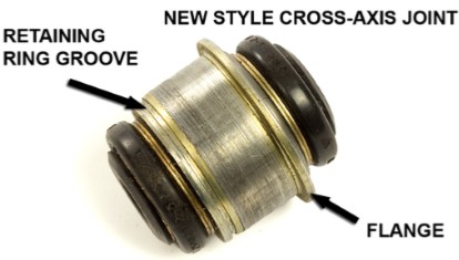
Ford recalled the IRS rear spindles in 1999 Mustang Cobras due to issues arising from the design of the cross-axis joints. All post-1999 Mustangs equipped with an IRS have the new style rear spindles. All of the older style rear spindles should have been replaced in the recall, but there still may be some floating around. The following comparison photos should help you identify what rear spindles you have.
Note: The MMIRSB-3 IRS Cross-Axis Replacement Joints are only compatible with the new style rear spindles
