Top Sellers in Mustang
How to Install a NX Nitrous Kit - Plate System on Your 1996-2004 Mustang GT
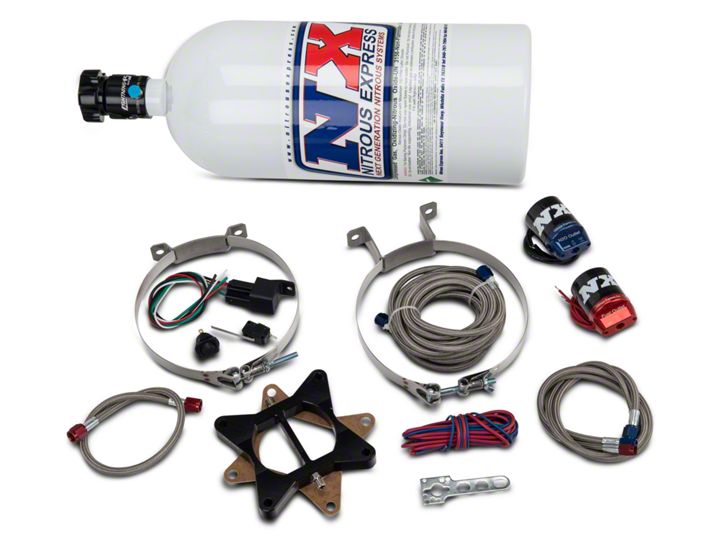
Shop Parts in this Guide
Installation
1. For clarity purposes, I removed the passenger seat. It’s not a requirement for installation, although it certainly provides you more area in which to work. If you do decide to remove the seat and it’s equipped with side airbags such as mine, keep in mind that you’ll want to follow the Supplemental Restraint System procedures laid out by Ford. These procedures will prevent accidental airbag deployment.
2. It’s always a good idea to disconnect the car’s battery when you’re planning on working on your car. This is especially true when you’re talking about work with a vehicle’s wiring. Using an 8mm wrench, loosen the nut on the negative battery cable, and then disconnect the cable from the battery post.
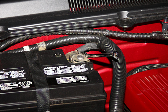
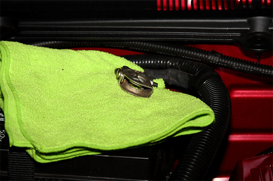
3. A good way to keep the cable from contacting the battery while you work is to place a cloth between the cable and the battery.
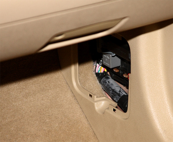
4. Next you’ll want to gain access to the passenger side kick panel, as that’s where the Mustang’s Smart Junction Box resides. You’ll see it behind the pop-off access panel, although to gain full access to the Smart Junction Boxwe’ll first need to remove a few interior panels.
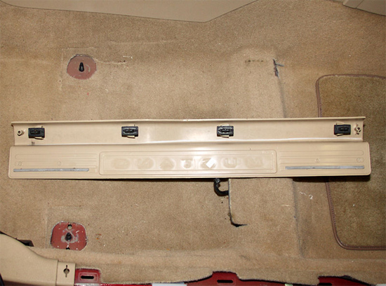
5. Remove the door sill trim plate by pulling up at its inner edge. The four clips (visible in the picture below) should pop loose with a little effort. There is also double-sided tape used to seal the plate to the body of the car. Once the clips have been popped loose, you can pull on the plate carefully, and the double-sided tape will separate from the car.
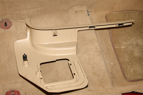
6. Next, remove the kick panel trim. It is held in place by four clips as well. You can see their locations in the picture below. It helps to have the square access panel removed, as it allows you to grip the kick panel a little easier. The lowermost clip will release by pulling the panel towards the center of the car, and the other three by pulling the panel towards the rear of the car.
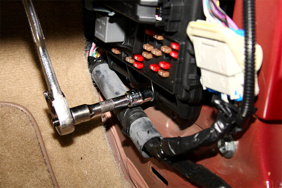
7. Now that you have access to the complete Smart Junction Box, use a 10mm socket and socket wrench to remove the single nut near the floor that holds it in place. You’ll want a longer socket for this, as a short socket will have problems reaching the nut.
8. Pull the lower end of the Smart Junction Box towards the center of the car, and then once it’s free pull the whole box down. The backside of the Smart Junction Box is where the One Touch Top Module is installed. So you may find it necessary to pull some of the surrounding wiring harness loose from the car to rotate the Smart Junction Box into a desirable position for you to access.
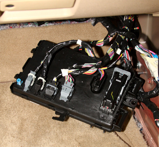
9. The first connections will be made using the wires coming from the large connector on the right-hand side of the Smart Junction Box. It may be necessary to remove some of the black tape to gain access to the wires. Find the red wire with the yellow stripe, and use a quick-splice connector to connect the yellow wire of the One-Touch Top Module to it. Notice that the quick-splice has one channel that is open and one that is closed. Place the red wire with the yellow stripe in the open channel and the yellow wire in the closed channel.
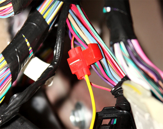
10. Use a pair of Channel Locks, or similar pliers, to fully press the metal tab into the connector. Do not use standard needle nose pliers as they can crush the connector. Once the metal tab is in the connector, snap the cover into place over the metal tab.
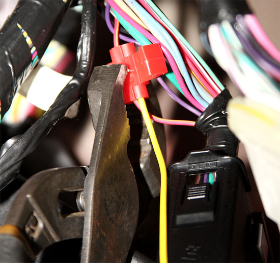
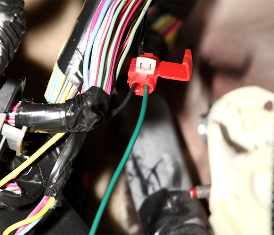
11. Next find one of the black wires, and use a quick-splice connector to connect the green wire of the One-Touch Top Module to it. Once the quick-splice’s tab is pressed in, snap the plastic cover into place.
12. For the next wiring connections, you’ll need to remove the third connector from the left-hand side. Swing the cam lever down, and carefully pull the connector out of the Smart Junction Box.
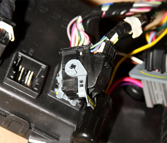
13. Clip the following two wires a couple of inches from the connector, and then strip the ends.
- Red with Black Stripe
- Yellow with Light Blue Stripe (DO NOTuse the Light Blue wire with the Yellow Stripe)
Connect the pair of wires that go to the connector with the white wire from the One-Touch Top Module. Twist a wire nut onto these wires to secure them all together. Make sure there is no bare wire exposed below the wire nut, and ensure that the wire nut is securely in place.
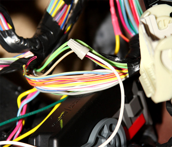
14. For the pair of wires on the harness side, use a wire nut and cap them off separately. Then carefully plug the connector back into the Smart Junction Box and rotate the cam lever back into place.
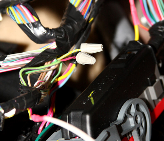
15. The last set of wires you’ll work with on the Smart Junction Box will be found on the leftmost connector. Rotate its cam lever, and remove it from the Smart Junction Box.
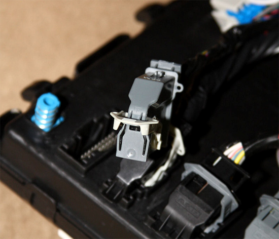
16. Cut the light blue wire with the orange stripe in two, and then strip the ends.
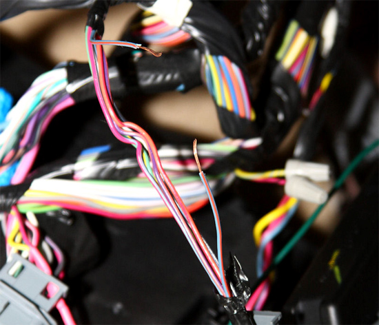
17. Connect the brown wire from the One Touch Top Module to the wire leaving the connector, and the red wire from the One Touch Top Module to the wire from the harness.
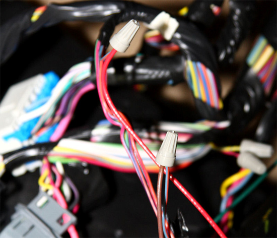
18. Then cut the violet wire with the orange stripe in two, and strip the ends. Connect the violet wire from the One Touch Top Module to the violet wire with the orange stripe leaving the connector.
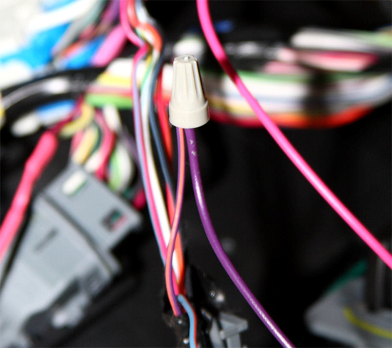
19. Connect the pink wire from the One Touch Top Module to the violet wire with the orange stripe from the harness.
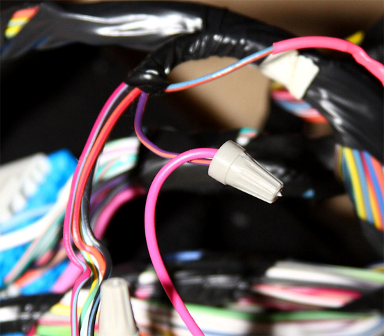
20. Carefully plug the connector back into the Smart Junction Box and rotate the cam lever back into place.
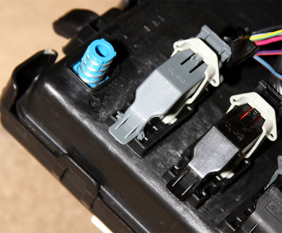
21. The black wire from the One Touch Top Module is for use with a light bar, allowing the third brake light to be disabled when the top is up. This wire is a ground wire, so the wire doesn’t need a wire nut. However, I went ahead and placed one on it for the future when a light bar is added. That way I already have the wire nut handy.
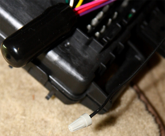
22. Now that the wiring job is completed, place the Smart Junction Box back where it came from. Push the top into place first, and then slide the bottom into place over the bolt. Tighten the nut back down to hold the Smart Junction Box into place, and then reinstall the interior panels that were removed. Once everything is back in place, reconnect the battery.
23. You’ll need to program the One Touch Top Module using the following instructions. Keep in mind, that you’ll program the Module for both directions of the top’s travel. You can program them independent of one another, as well as in any order.
Programming "Top Down" Function
1. Start with the top up, and the top latches released.
2. Press the top down side of the switch six times, after which the top will revert back to the closed position.
3. Press and hold the top down side of the switch, until the top is completely down. Once it’s down, release the switch.
4. You’ll see the top raise, and then lower itself back down. This confirms it’s properly programmed.
Programming "Top Up" Function
1. Start with the top completely down.
2. Press the top up side of the switch six times, after which the top will revert back to the down position.
3. Press and hold the top up side of the switch, until the top is completely closed. Once it’s closed, release the switch.
4. You’ll see the top reopen slightly, and then close itself. This confirms it’s properly programmed.
Final Notes:After the One Touch Top Module is programmed, simply pressing and releasing the appropriate side of the convertible top up or down switch will raise or lower the top as needed. No other input is required. You can stop the motion by pressing the switch again, or hold the switch down to use the convertible top as it was used prior to the One Touch Top Module’s installation. Note that when the top is raised, the motor will run for a few seconds after it’s closed to make it easier for you to fasten the top’s latches. Also, just as before, the top will still require you to have the vehicle stopped before it will operate as a safety precaution.
Installation instructions provided by AmericanMuscle customer Eric Hege 1.27.09
Top Sellers in Mustang
Related Guides
-
Installation
-
Installation
-
Installation
