
How To Install a Procharger Stage II Intercooled Supercharger System (11-14 GT Mustang)
Installation Time
1 days
Tools Required
- 3/8” Socket Set (Standard and Metric)
- 1/2” Socket Set (Standard and Metric)
- 1/2” Breaker Bar
- 4” Extension
- Torx Wrench
- Open End Wrench Set (Standard and Metric)
- 3/8” Allen Wrench Set
- Flathead Screwdriver
- Phillips Head Screwdriver
- Plier Set
- Hydraulic Jack
- (2) Jack Stands
- Electric Drill (optional)
- Soldering Gun (optional)
- Engine Coolant (optional)
- Electrical Tape (optional)
- Loctite (optional)
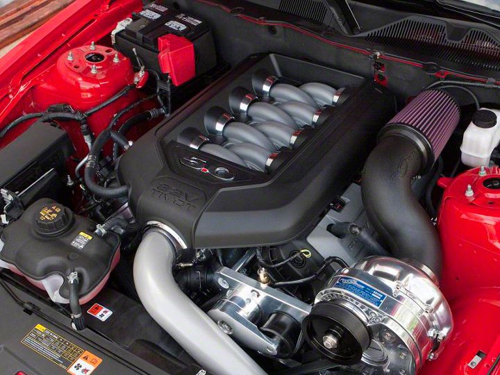
Shop Parts in this Guide
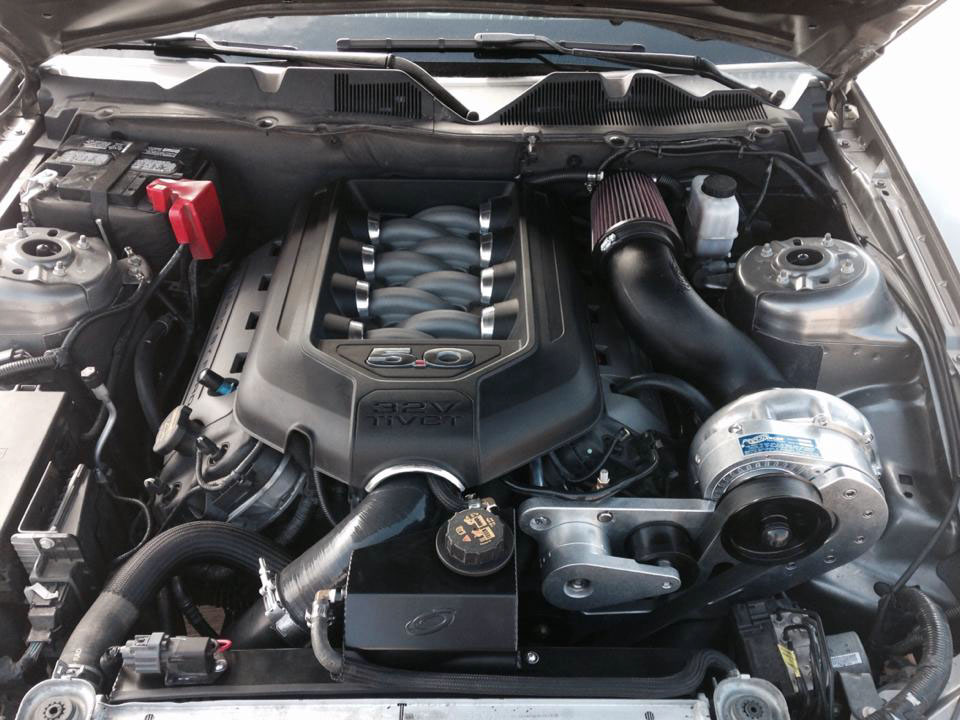
Installation Time: Approximately one day. Installed on 2012 Mustang GT 5.0/Manual
Required Tools
• 3/8” Socket Set (Standard and Metric)
• 1/2” Socket Set (Standard and Metric)
• 1/2” Breaker Bar
• 4” Extension
• Torx Wrench
• Open End Wrench Set (Standard and Metric)
• 3/8” Allen Wrench Set
• Flathead Screwdriver
• Phillips Head Screwdriver
• Plier Set
• Hydraulic Jack
• (2) Jack Stands
• Electric Drill (optional)
• Soldering Gun (optional)
• Engine Coolant (optional)
• Electrical Tape (optional)
• Loctite (optional)
Fuel System Purge
1. Open the hood on the vehicle and prop it in place.
2. Start by opening the fuse box and removing the #13 fuse for the fuel pump.
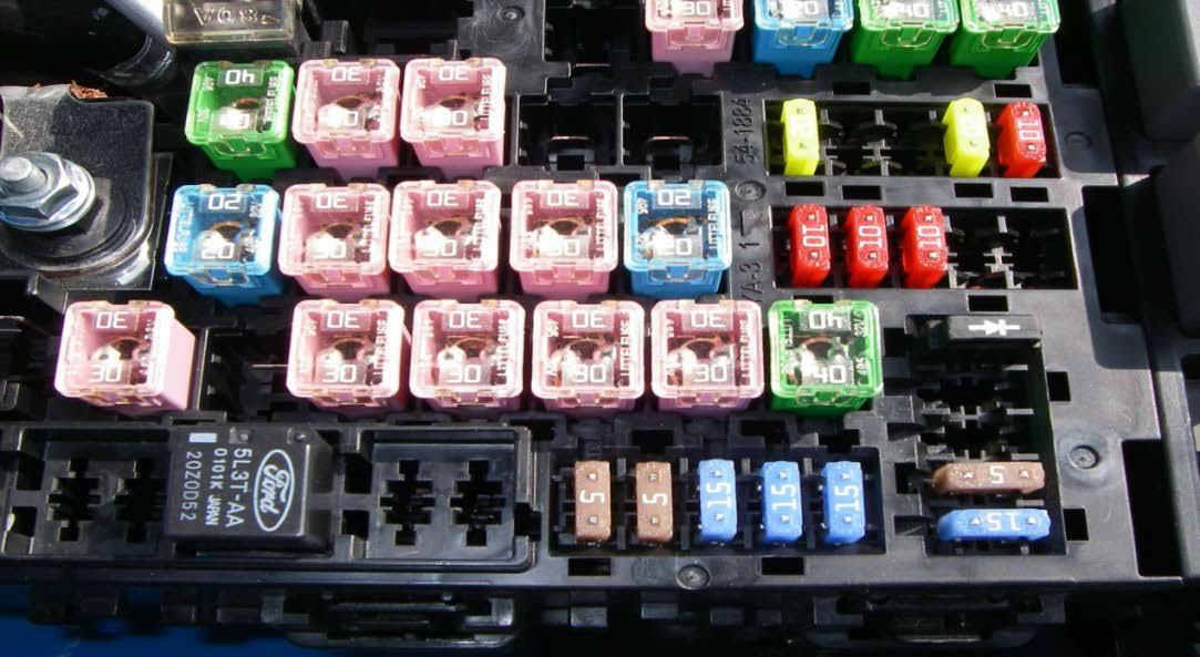
3. Next, start the engine and allow it to run until it stalls out. Then crank the engine over for 5 seconds to relieve the remaining fuel pressure.
4. Disconnect the battery ground and replace the fuel pump fuse.
Air Inlet and Box Removal
1. If your car has a strut tower brace, this is the time to remove it. Use a 13mm socket to remove the four bolts holding it in place and remove the brace.
2. Remove the engine cover by pulling straight up on it.
3. Use a 5/16 socket and loosen the intake inlet tube connection to the throttle body.
4. Next, use a 10mm socket to remove the bolt securing the inlet line to the driver’s side firewall. Once the bolt is removed, simply pull the line out of the firewall.
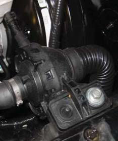
5. Now push in the new grommet into the hole in the firewall.
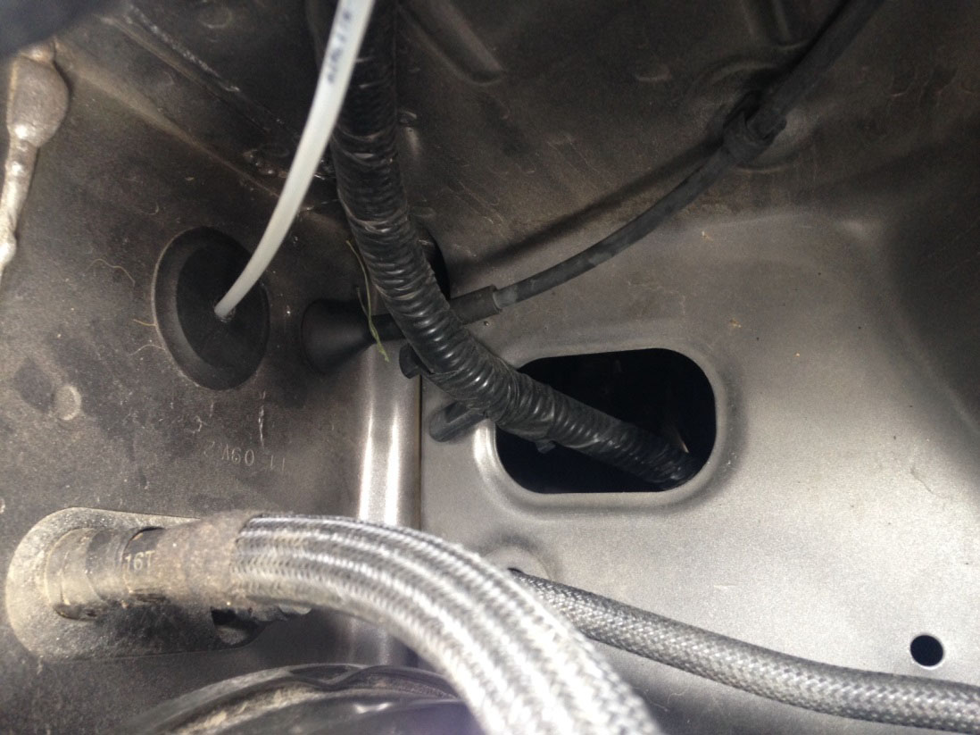
6. Unplug the PCV line connected to the driver’s side cylinder head. Unplug the MAF sensor and remove the harness from the intake tube.
7. Remove the air box from the car. Remove the bolts holding the lower portion of the box to the car using a 10mm socket. Now just lift up on the box and remove from car.
Bumper Cover Removal
1. Remove the 8 push pins holding the upper trim piece in place.
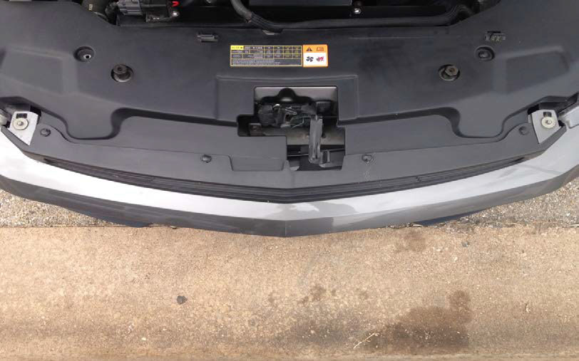
2. At this time raise the vehicle using a hydraulic jack and two jack stands.
3. For easier access to the bumper bolts, I removed my front wheels.
4. Next start removing the lower trim piece located underneath the vehicle by using a 7mm socket to remove the 9 bolts.
5. Using an 8mm socket, remove the 3 bolts holding the oil service panel in place and let it hang down. (Mine only had 2 holding it on and there are arrows pointing to the bolts)
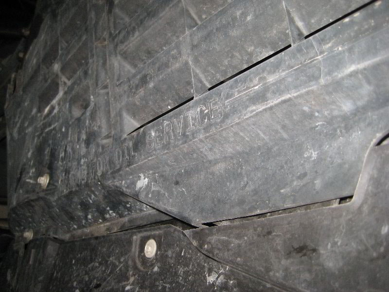
6. Use a 7mm socket to remove the 2 inner fender well bolts on each side.
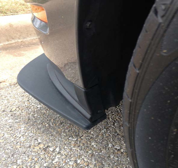
7. Remove the 2 upper bumper bolts using an 8mm socket.
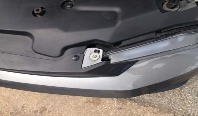
8. Now, from whatever angle works best for you, reach in and unplug the fog lights if you have them and unplug the side markers located in the bumper. You will also need to unclip the ambient air temperature sensor from the lower fascia.
9. Remove the drivers and passengers side plastic radiator shrouds by pulling out the pins holding them in. You will not reinstall these.
10. At this time, I left my vehicle on the jack stands and continued to install the kit. If you would like, you can put the wheels back on the car and lower it back down to make the next steps easier. (If you are tall and can access all parts of the engine while it’s jacked up, just leave it on the stands).
Fuel Injector Installation
1. Using a 10mm socket, remove the 4 nuts securing the plastic fuel rail bracket. After the nuts are off, remove the bracket and the 2 foam insulators from around the fuel rails.
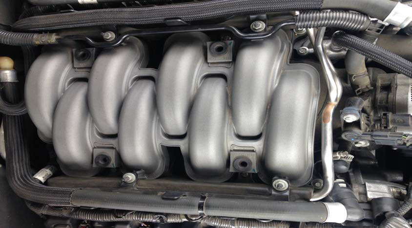
2. Now you will need to pull the coolant lines out of the way so you can remove the fuel rails.
3. Locate the fitting on the driver’s side of the car, where the metal fuel rail connects to the rubber fuel line. Grab a rag and place it under this location. To remove the fuel supply, simply push the 2 blue tabs together and pull the fuel line from the fuel rail. Some gas may leak at this time but that is what the rag is for.
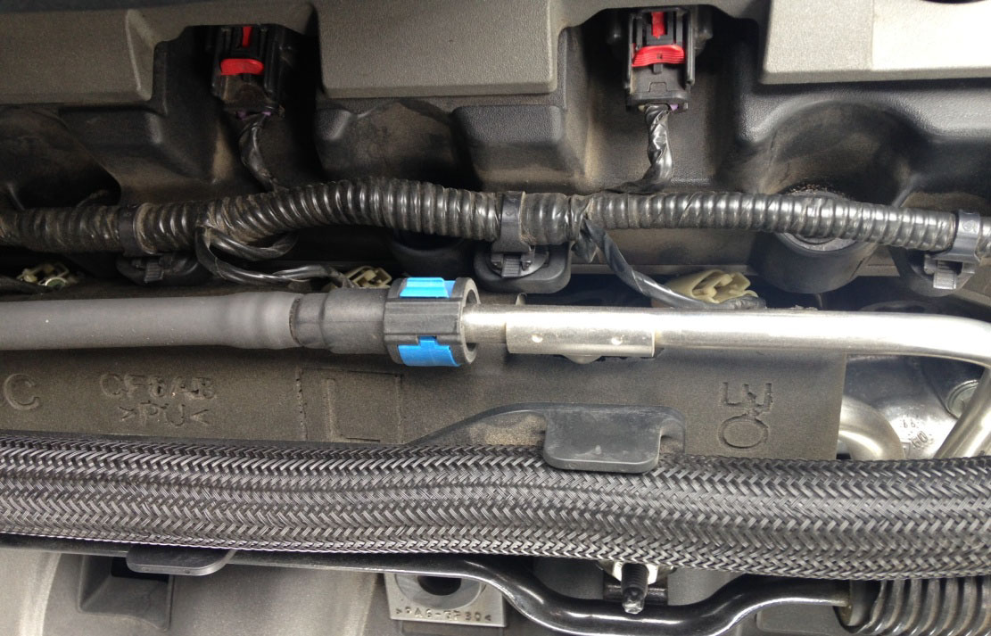
4. Unplug each fuel injector connection. You may label them if you would like to be safe but it is very difficult for them to be plugged into the wrong one when reinstalling.
5. Using a 10mm socket, remove the 4 fuel rail bolts.
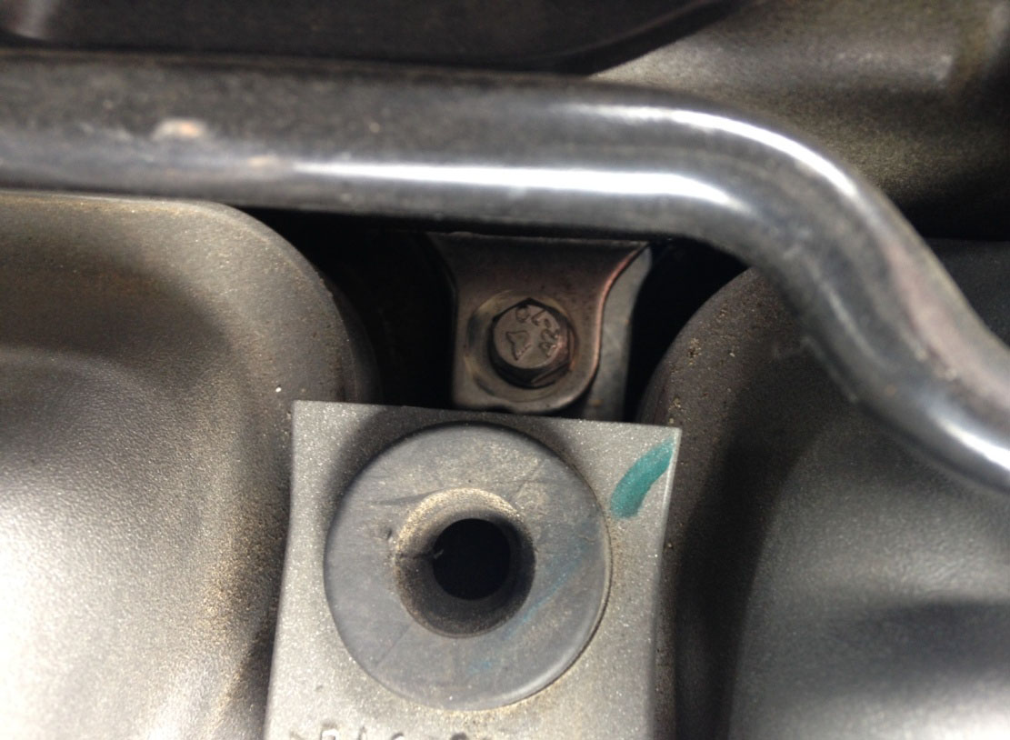
6. Pull straight up on the fuel rail to remove it. Make sure the injectors are still attached and lay it upside down on a clean dry surface.
7. Next you will need to remove the injectors from the fuel rail. To do this, spread the retaining clips apart on each injector and simply pull the injector out. I did one side at a time. Remember which way the injector plugs are facing when you remove them and install the new ones in the same direction.
8. Now it is time to install the new injectors. Lubricate each new injector o-ring with a clean drop of engine oil. To install, push the injector into the fuel rail and lock it in place with the retaining clips. Remember to face the plugs outward.
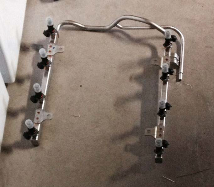
9. Back to under the hood, remove the 4 stock fuel rail spacers that the fuel rail sits on. The best way is to pull up on them using a pair of pliers.
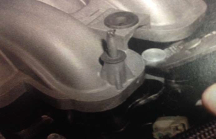
10. Locate the new fuel rail spacers in the kit and place these where you removed the stock ones. Align the fuel rail back on the vehicle and lightly press down to get the injectors in place. Using the 4 supplied M8-1.5x80mm bolts and washers, bolt the fuel rail down.
11. Now you can plug in each of the injectors. Plug the supply line back into the fuel rail at this time and reinstall the fuel rail insulation and plastic brackets.
Crank Pulley Installation
1. Remove the 2 bolts securing the coolant overflow tank to the radiator shroud using a 10mm socket.
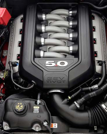
2. At this time I recommend using a pair of pliers to remove the clamps holding the coolant lines to the overflow tank. Take the lines off one at a time, plug the lines with a rag and push to the side. The easiest way to save coolant in your tank is to flip the tank upside down, plug the holes on the tank, and set to the side.
3. Now that the coolant tank is out of the way, reach down and unplug the radiator fan on the passenger’s side of the car. Using a 10mm socket, remove the 2 bolts holding the fan/shroud to the radiator. Lift the fan/shroud up and remove it from the car.
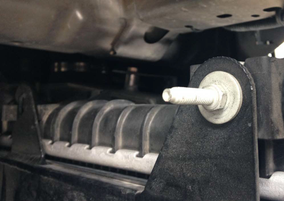
4. With the fan/shroud out of the way, the next step is to remove the harmonic balancer bolt using an 18mm socket and breaker bar. If you have an impact gun, I recommend using it. If not, breaking it loose is not that hard. I did it without the impact gun. You will not reuse the stock bolt but you will reuse the washer.
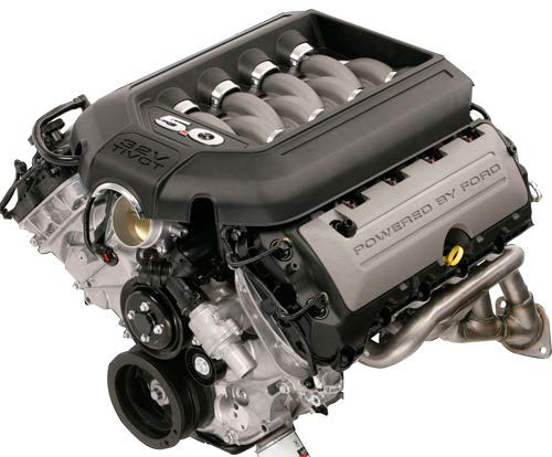
5. Here comes the tricky part. It is now time to mount the new crank pulley to the harmonic balancer. The crank pulley uses cam lock bolts to hold it on to the balancer. With the cams loose, put the pulley onto the balancer making sure that the cam bolts are aligned correctly between the harmonic balancer spokes. Turn the pulley clockwise until the cam bolts prevent it from moving any further.
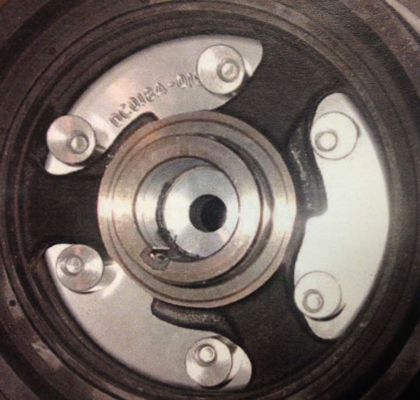
(Even though you will not be able to see this on your car, this is the back view of the harmonic balancer with the crank pulley installed. DO NOT REMOVE THE HARMONIC BALANCER! It is not necessary.)
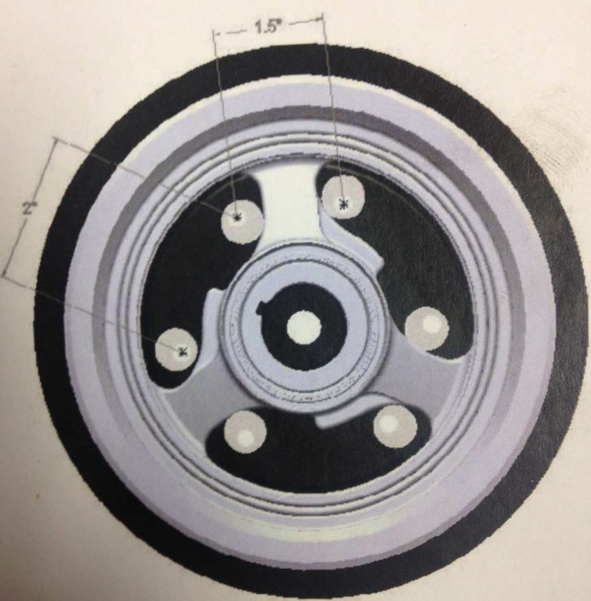
6. Make sure to install the pulley so it has very little rotational play. The picture above shows the correct way to install it.
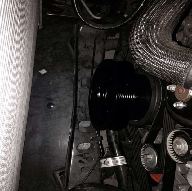
7. Use the stock crank bolt washer and slide it onto the new crank bolt. The bolt is M12-1.5x120mm and comes in the kit. Now use a 19mm socket and a torque wrench to tighten the bolt to 35 ft-lbs. Grab a white paint marker to mark the position of the bolt then tighten the bolt an additional 90 degrees.
8. Now tighten the 6 cam bolts onto the harmonic balancer with a 1/2” socket and 4” extension.
Cooling System
1. Unplug and remove the fan controller from the stock fan. Mount the fan controller to the new fan shroud using the new 1/4-20x5/8 bolt and washer.
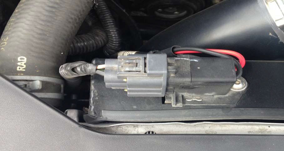
2. Mount the new fan to the new fan shroud. Set the fan on top of the shroud from the engine side and bolt it down using the four 1/4” bolts, nuts and washers.
3. Here comes the next tricky part. The new fan plug will not fit into the factory harness so you must modify it or cut it off. To modify it, grind the edges of the spade terminals down until they fit into the plug. I chose to simply cut the new plug off, strip the wires and connect the two red and two black wires and wrap them in electrical tape. Either method will work just fine.
4. Install the new fan shroud with fan the same way you removed the stock one and tighten the 2 bolts back down using a 10mm socket.
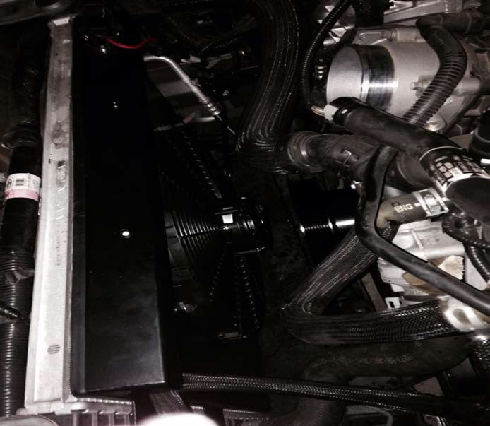
5. Grab the new coolant reservoir and install the 3 brass barb fittings in the holes on the reservoir. The 3/8 barb fittings are for the top of the tank and the 3/4 barb fitting is for the bottom. Before installing them, make sure to use some sort of thread sealer like pipe dope or plumbers tape. Don’t use too much and do not over tighten.
6. Cut the stock coolant reservoir hoses to fit the new tank. Make sure the hoses are not stretching to reach the fittings and make sure they are not too long so they get in the way. Use the #6 hose clamps to secure the two 3/8 lines to the tank and use the #12 hose clamp to secure the bottom 3/4 line.
7. Now it is time to mount the coolant reservoir to the radiator shroud using the two 1/4-20x5/8 bolts.
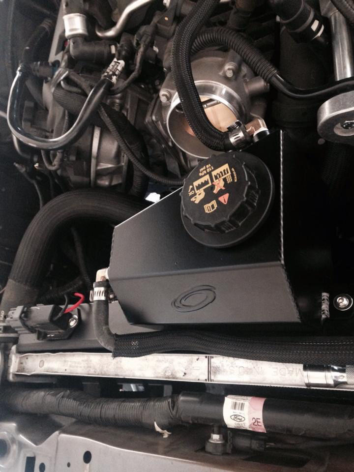
8. Now that the coolant reservoir is in place and all hoses are connected properly, make sure the coolant lines do not interfere with the belts. Fill the coolant tank with the coolant you saved from the stock tank or fill it with new ford coolant. You may need to add more coolant once the car runs through its first heat cycle after it is started.
Procharger Bracket and Head Unit
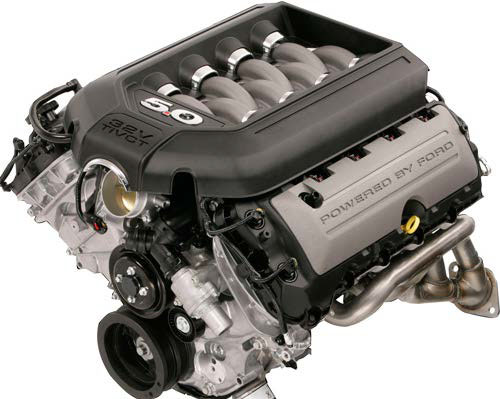
1. Remove the 4 bolts that have arrows pointing to them in the image above. The lower right nut is the top alternator nut and can be removed with a 15mm socket. The one directly above it will have a plastic cap that will need to be removed to take the bolt out. The remaining bolts can be removed using a 13mm socket.
2. You may need to bend the upper coolant tube out of the way to access the top bolt. If you do, be careful not to crack it.
3. There will be a stud in the location where you removed one of the nuts in the previous step. This is where you will screw on the 3.625” long hex spacer. Use a 3/4 wrench to tighten this spacer.
4. If your kit comes with an oil drain line, this is the time to thread it into the bottom of the head unit and make sure the plug in the end of the line is tight.
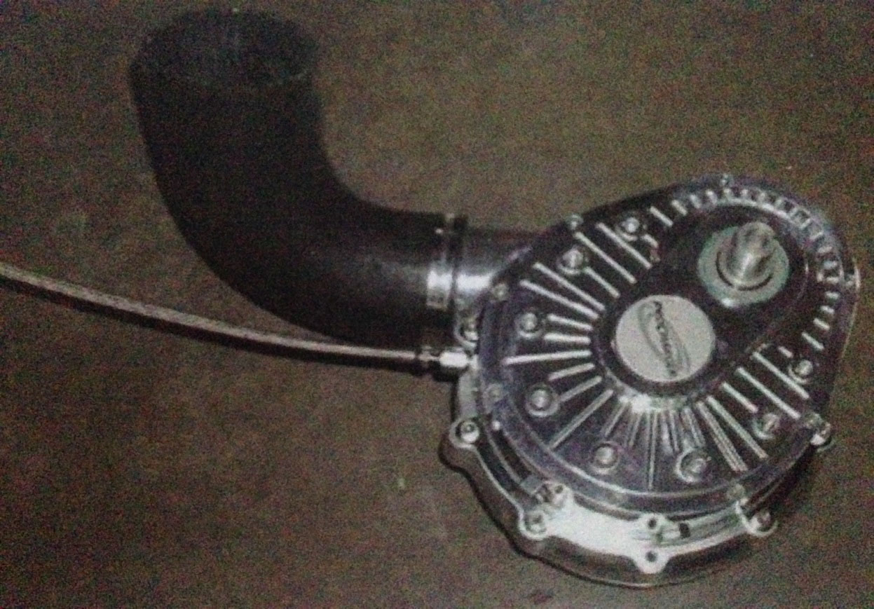
5. Remove the oil fill reminder tag from the head unit. Mount the Procharger Head Unit to the bracket using the four 5/16-18x1 and two 3/8-16x1.25 bolts. Make sure they are tight and I suggest using a little bit of Loctite.
6. At this step, I mounted the 90 degree coupler to the head unit and tightened it down because it is way easier to access while off the car. Use the short end of the elbow to mount on the discharge end of the head unit as pictured above.
7. Mount the main bracket loosely on the car using the M10-1.25x25mm bolt and washer into the hex spacer you installed previously.
8. Now slide the 1.745” idler shaft spacer between the bracket and the stock idler pulley. Use the M8-1.25x80mm bolt and washer to tighten this down.
9. Slide the two 4.313” spacers between the bracket and the engine. Use the M8-1.25x180mm bolts and washers to tighten them down. You may now fully tighten all the nuts and bolts securing the bracket to the engine.
• Use the guide below for references on the locations of the spacers and bolts.
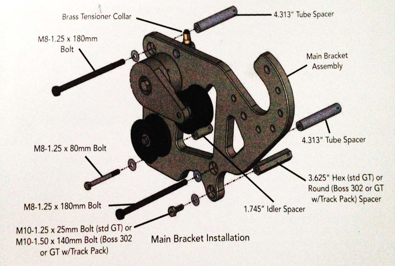
10. Once the bracket and head unit are installed on the car, fill the supercharger with 1 six ounce bottle of procharger oil. Route the drain line to under the car where it is easy to access and zip tie it in place.
11. Loosen the bolts on the back of the tensioner and install the supercharger belt.
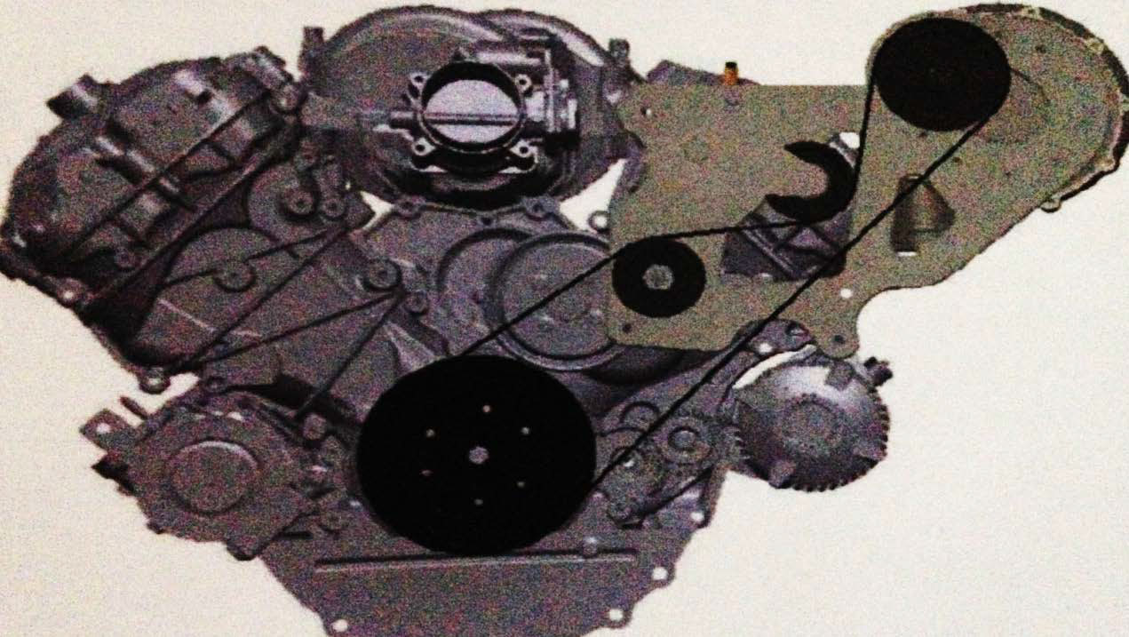
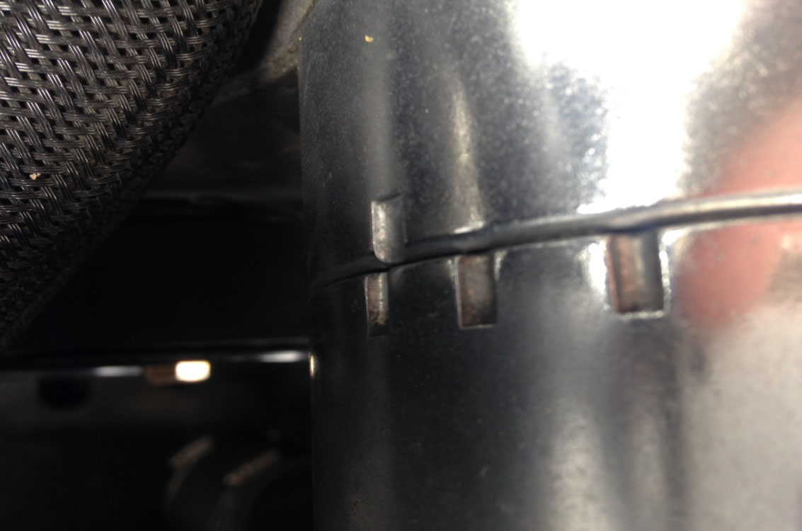
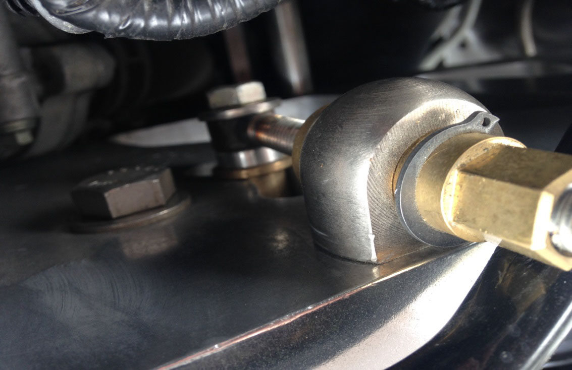
12. Tighten the belt by turning the brass tensioner counter clockwise until the first set of etched marks on the tensioner body align. Now tighten the two bolts on the back of the tensioner using a 3/4” and 9/16” wrench.
Intercooler
1. Remove the mass airflow sensor from the stock airbox. Once removed, slide it into the new intercooler. Make sure the arrow on the MAF points down and towards the passenger’s side of the car. Tighten it down using the two M4-.7x12mm bolts.
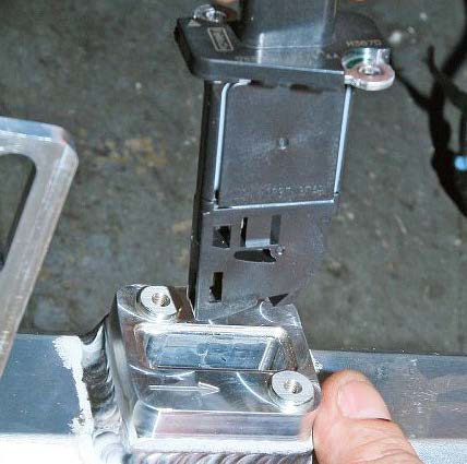
2. Install the metal bracket to the top tabs on the intercooler using the 3/8-16x1 bolts, washers, and nuts.
3. Remove the 2 bolts securing the hood latch to the car using a 10mm socket.

4. Mount the intercooler with bracket on to the car by lining up the intercooler bracket with the two holes from the hood latch assembly. Use the stock bolts to install but do not tighten all the way down.
5. Locate the lower intercooler brackets. Mount the driver’s side intercooler bracket to the intercooler using the 5/16-18x1 bolts, washers, and lock nuts. Place a spacer on the back side of the longest bolt holding the bumper to the car. Slide the open end of the bracket onto the bolt end and tighten using the M8 washer and lock nut.
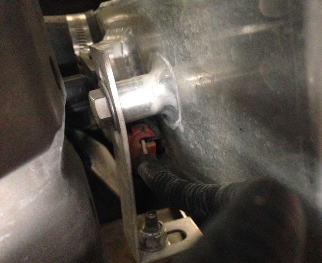
6. Now do the same thing for the other side and test fit the bumper cover to check the clearance. Once clearance is good, tighten all of the intercooler bracket nuts and bolts.
7. Plug in the MAF wiring harness extension to the factory plug. Route the harness behind the intercooler and plug the other end into the MAF sensor.
Intercooler Tubing
1. The best way to install all of the intercooler tubing is to refer to the assembly schematic on the following page. Each coupler connection will be secured with a #52 hose clamp except for the throttle body tube which uses two 3.75” t-bolt clamps. Keep all of the clamps semi-loose until all the tubing is installed into the correct position. Then go back and tighten the clamps all the way down.
2. If you did not install the 90 degree elbow onto the discharge of the head unit in the previous step, now is the time to do it. Mount the short end onto the head unit and route the long end under the supercharger bracket. There is a cutout for the elbow to go through.
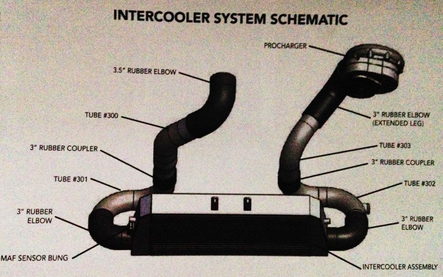
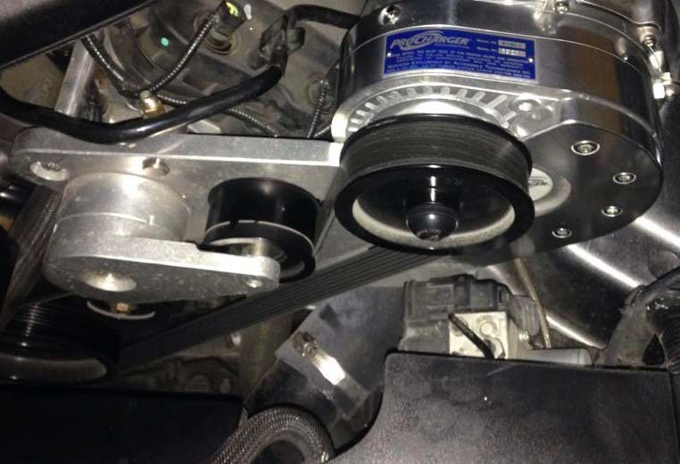
3. Install the shorter straight end of the blower discharge tube #303 into the open end of the coupler from the previous step. Slide the longer section of the 3” coupler onto the end of this tube.
4. Mount the surge tube #302 onto the open end of the rubber coupler from the previous step. Now complete the connection to the intercooler using a 90 degree rubber elbows.
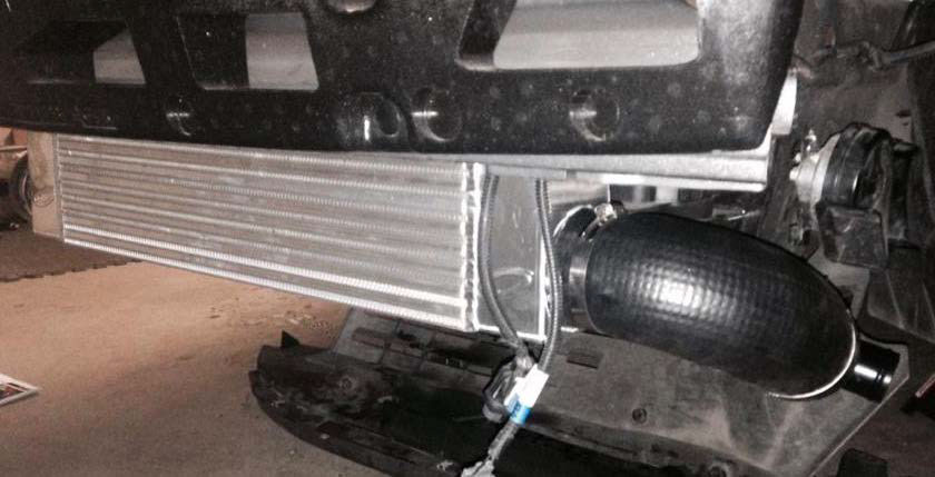
5. Mount the 3” 90 degree coupler onto the discharge side of the intercooler.
6. Mount the double 90 degree tube #301 onto the open ended coupler from the previous step. Attach the 3” diameter, 3” long coupler to the end of this tube.
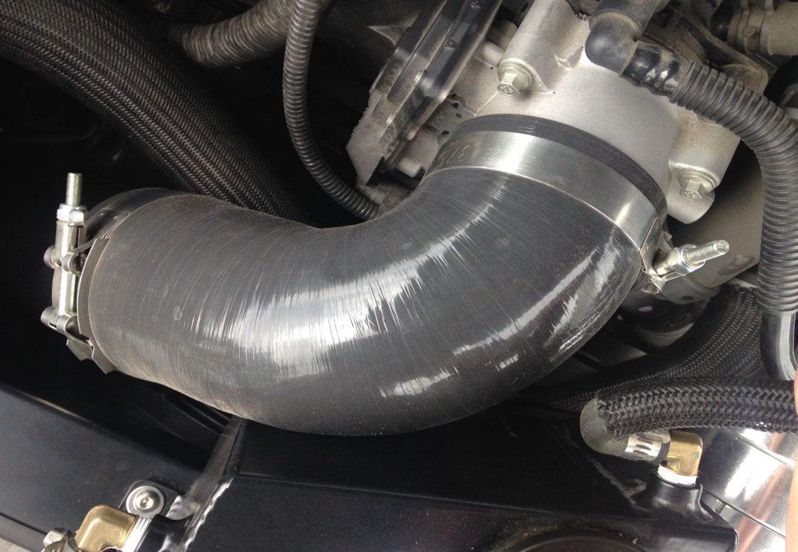
7. Now slide the throttle body tube #300 onto the open end of the coupler from the previous step. Slide the 3.5” 90 degree coupler onto the end of the tube and connect it to the throttle body.
8. Find the surge system bag that comes in the kit. Slide the 1-1/2” 90 degree coupler onto the open bung on the surge tube. Slide the surge valve onto the open end of the coupler followed by the supplied filter. Tighten the connections with the #24 hose clamps.
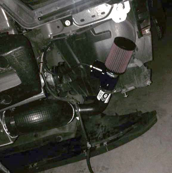
(I installed the filter at first, but after I completed the install, I removed the filter to get more of a blow-off-valve sound)
Vacuum Manifold
1. Locate the 3/8” brake booster hose that runs along the back side of the engine near the firewall. The line is connected to the brake booster located on the driver’s side.
2. Use a hose cutter and cut a 3-1/2” long suction out of the hose.
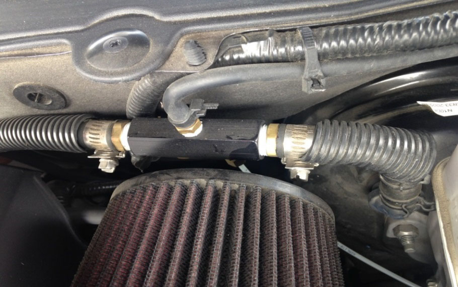
3. Now assemble the vacuum manifold using the barb fittings and plugs. Install the vacuum manifold and clamp in place using the #6 hose clamps.
4. Attach the 3/16 vacuum hose to one of the 3/16 barb fittings on the vacuum manifold. Now route the hose back to the surge valve and slide onto the vacuum port.
5. If you are not going to use a boost gauge, remove the extra 3/16 barb fitting and replace it with a plug. Use zip ties to secure vacuum hoses to their fittings.
PCV and Air Filter
1. Slide a 5/8” rubber cap onto each open bung located on the intake manifold and passenger side valve cover. Secure the intake manifold cap with a #10 hose clamp.
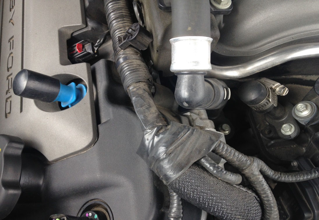
2. Now locate the 5/8” hose. Trim the 90 degree elbow to fit on the open bung on the driver’s side valve cover. The other end of the hose will connect to the intake tube in the next step.
3. Slide the air filter onto the end of the intake tube. Slide the section of 3-3/4” rubber coupler onto the other end of the intake tube.
4. Trim the 5/8” PCV hose from the previous step to properly fit onto the brass bung on the intake tube. Slide the intake tube into place, sliding the open end of the 3-3/4” coupler onto the inlet of the head unit. Make sure there are no kinks. Tighten the intake tube down using the two #64 hose clamps.
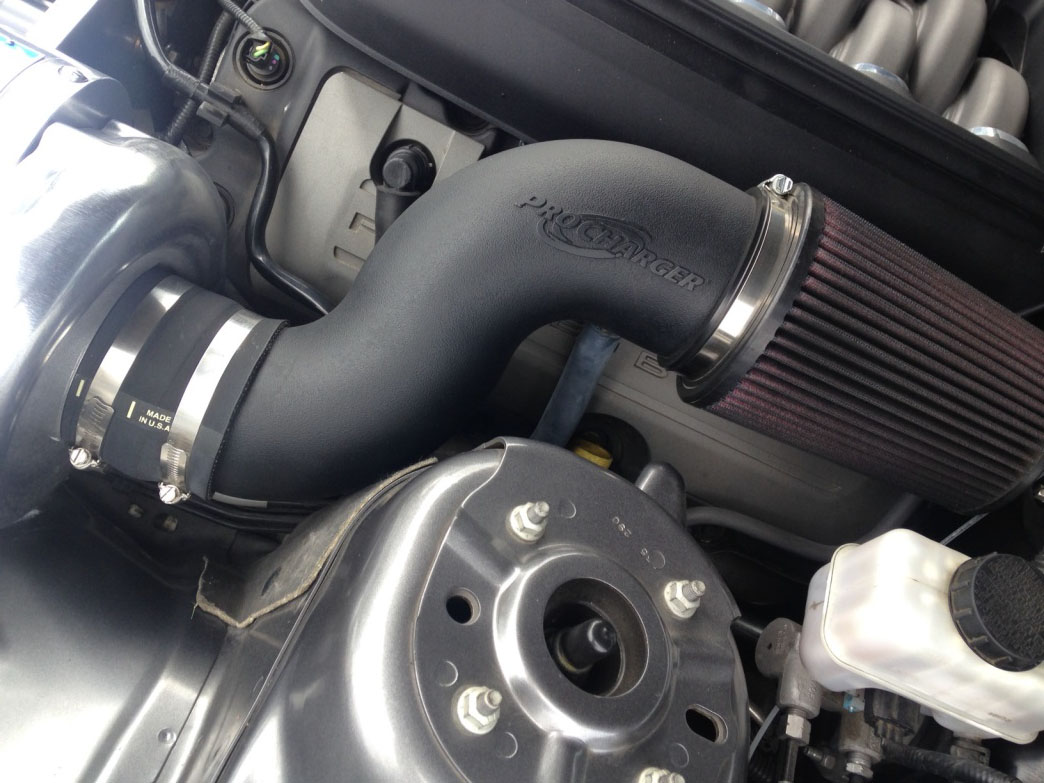
The basic installation is complete. Now it is time to put the car back together.
Finishing The Job
1. Check over all of the work and steps done in the installation process. Make sure there are no loose nuts or bolts. Check the belt tension and make sure the hoses do not interfere with the belts.
2. Now it is time to reinstall the front bumper cover. Serious trimming may be required to make the bumper fit over the large intercooler. I spent hours cutting and test fitting my bumper before it was right. This is the most difficult part of the entire process.
3. Plug the fog lights and marker lights back into the bumper. Clip the ambient air temperature sensor back into the bumper.
4. Remount the oil service panel and lower plastic trim using the stock hardware.
5. Reinstall the wheels
6. Reinstall the upper plastic trim using stock hardware.
7. Reinstall the engine cover by pushing it straight down onto the engine.
8. Reconnect the battery.
9. Load the tune. If your kit came with the SCT programmer, now is the time to plug the tuner into the OBDII port on the car. Follow the instructions on the screen. Then select program vehicle, load custom tune, select tune and follow instructions.
You have now completed the installation of the ProCharger Stage II Intercooled supercharger kit!
Installation Instructions written by AmericanMuscle Customer Joshua Blackford 10.5.2014

