FREE 1 to 3-Day Delivery on Orders $119+ Details
Best Sellers


How to Install Roush Styling Bar - Dark Charcoal (05-14 All) on your Ford Mustang
Installation Time
30 minutes
Tools Required
- ⅜” Drive Ratchet
- ⅜” Drive 3” Extension
- ⅜” Drive 10mm Socket
- ⅜” Drive 13mm Socket
- T-50 Torx Bit
- Trim Tool (Fork Tool)
- Heat Gun (or similar heat source)
- ¼” Allen Wrench (4” long, ball-ended recommended)
- Center Punch
- ½” Wrench
- Solder
- Solder Iron
- Drill Motor
- ⅛” Drill Bit
- 5/16” Drill Bit
- 2” Hole Saw
- T-20 Torx Bit
- Wire Crimpers
- Wire Strippers/Cutters
- 3/16” Allen Wrench
- Hammer
- Shop Vacuum
- Electrical Tape
Installation Instructions
Before installing your ROUSH Performance Product(s), read through the entire installation procedure and check to make sure all items are present. Contact ROUSH Customer Service at 1-800-59-ROUSH, weekdays from 9:00 AM to 5:00 PM EST, with any questions regarding fit, missing parts or instructions that are unclear to you.
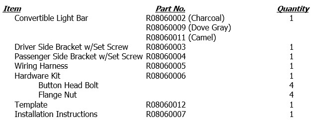
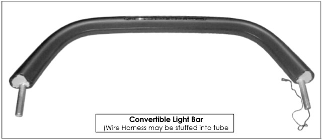
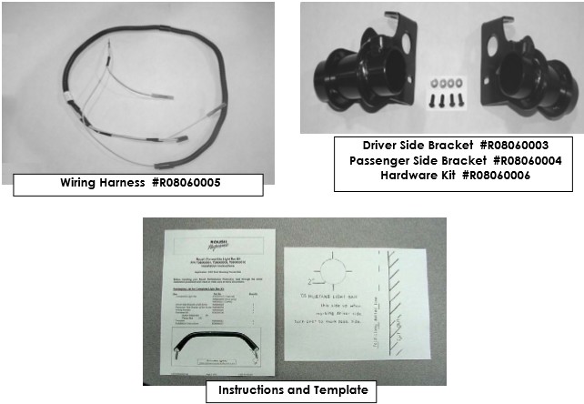
Packaging List for Complete Light Bar Kit
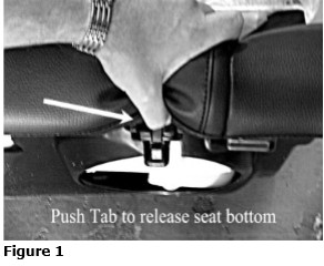
1. Remove Back Seat:
A) Locate the retainers securing the seat bottom into the vehicle, approximately 10 inches from the end of the cushion, either side. Use your thumb to push in retainer release tab. Lift the seat up to remove. Refer to Figure 1.
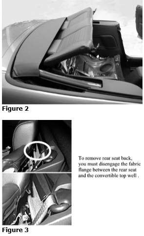
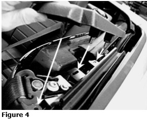
B) Remove the two 13mm screws securing the seat back, located on each lower corner. Lift seat upward to release seat back from brackets at the top. You can carefully prop the seat back under the retracted top. Refer to Figure 2. Use caution if choosing this method not to damage or scratch the vinyl of the seat. You can remove the seat from the vehicle completely by disengaging the flanges securing the top of the rear seat to the fabric of the convertible top well. Refer to Figure 3.
2. Remove Quarter Trim Panels:
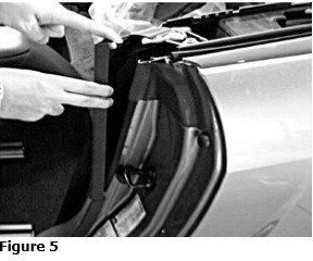
A) Grip the Quarter Trim Panel Cap at the shoulder strap opening and lift up to dislodge the retaining clips. Refer to Figure 4.
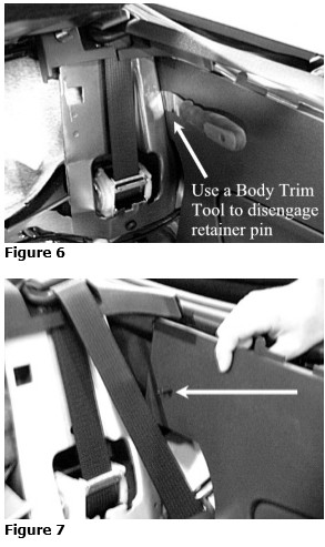
B) The inside Quarter Trim Panels are two-piece panels. Remove the upper portion of the Quarter Trim Panel from the vehicle; it is not necessary to remove the lower portion. Pull the forward edge of the trim Panel over the pinch weld in the doorjamb. Use a Door Trim Tool (Fork Tool) to dislodge the pushpin retainer at the rear edge of the Trim Panel approximately 4” down from the top, pry Trim Panel toward the outside of car to release retainer. Refer to Figure 5.
C) Use a Door Trim Tool (Fork Tool) to dislodge the pushpin retainer at the rear edge of the Trim Panel approximately 4” down from the top, pry Trim Panel toward the outside of car to release retainer. Refer to Figures 6 & 7.
3. Install Light Bar Brackets:
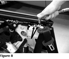
A) Remove the shoulder belt guide retaining bolt with a T-50 Torx Bit. Remove the 10mm head bolt directly behind the shoulder belt guide. Refer to Figure 8.
B) Install the Light Bar Bracket to the vehicle using the factory bolts removed in the above step. Refer to Figure 9.
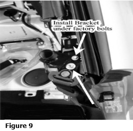
Note: It is imperative that the shoulder strap guide bolt spacer fit inside of the clearance hole of the Light Bar Bracket so that the seat belt functions properly and the Light Bar Bracket fits properly.
Note: Torque seat belt guide bolt (T-50 Torx) to 30lb-ft.
C) Remove the four (4) Speaker fasteners with a T-20 Torx bit and remove the speaker. Move speaker away from the general area to keep drill shavings from sticking to the speaker magnet.
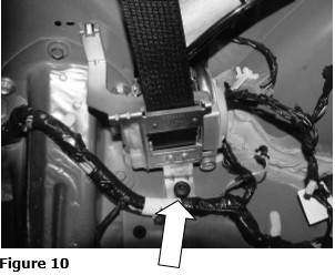
D) Remove the belt retractor retaining bolt with a T-50 Torx bit. Refer to Figure 10. Lift up on the base of the retractor and detach top hook. Place retractor out of way of any debris.
E) With the Light Bar Bracket in place and secured by the 10mm head bolt and the shoulder strap guide bolt reinstalled and tight, center punch through the two Bracket attachment holes. Drill ⅛” pilot holes through Bracket hole into sheet metal. Enlarge pilot holes to 5/16”. Refer to Figure 11.
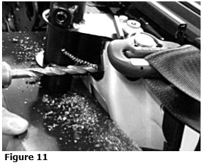
Note: It is very important that you protect the Seat Belt and the Shoulder Strap Retractor from the cutting debris that is created during the drilling process. We recommend using a Rag to cover the Retractor to keep debris out of the mechanism during drilling.
F) Using the Shop Vac, vacuum up any metal shavings.
G) Reinstall belt retractor and torque T-50 Torx fastener to 30 lb-ft.
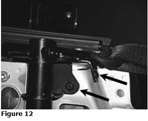
H) Install the Button Head Screws through the Bracket, securing Bracket to the vehicle, and tighten to 18 lb-ft. Refer to Figure 12.
I) Reinstall the Drivers Side upper portion of the Quarter Trim Panel. Install only the pushpin retainer portion or the Passenger Side Quarter Trim Panel.
4. Cutting holes in Quarter Trim Panel Caps:
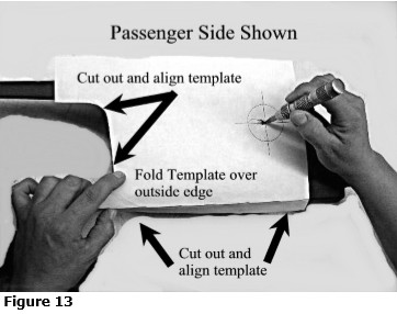
A) Cutout the Template (supplied in kit) and place on the Passenger Side Trim Panel Cap and align as directed on the Template. Refer to Figure 13. Center punch the 2” hole center point, remove the template and drill an ⅛” pilot hole. Follow in the pilot hole with a 2” Hole Saw.
B) Flip the Template over and place on the Driver Side Trim Panel Cap and repeat the above steps for marking and drilling the 2” hole.
5. Reinstall Quarter Trim Panel Caps:
Install the Drivers side Trim Panel Cap and loosely install the passenger side Cap (do not fully clip into place). Verify that the 2” holes drilled in step #4 do not obstruct the Light Bar Bracket receiver tube. If the receiver tube is blocked, trim the Cap as necessary to achieve an unobstructed path for the Light Bar to install into.
6. General Wire De-pinning Procedure
Note: The directions and pictures in the following are for illustration only and do not exactly represent any of the exact connectors that are part of this procedure. Use extreme care when trying to de-pin a wire, the process does not require very much force. If too much force is applied, the locking tab will break. Without a functioning locking tab, there will be no way to retain the wire/pin in the connector body and it will pull/vibrate out of the connector.
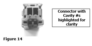
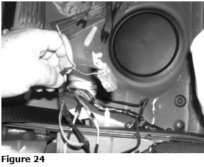
A) Verify that the correct wire and cavity location have been chosen. Refer to Figure 14.
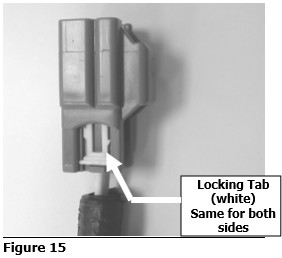
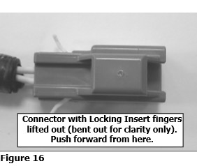
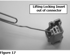
B) Remove the locking insert by lifting its tab from both sides of the connector body. Refer to Figures 15 & 16. Slide forward until both are fully into the body of the connector. Using a pick tool or paper clip, lift the locking insert out of the face of the connector. Refer to Figure 17.
C) Holding a very slight tension on the wire you intend to remove, insert a pick tool or paper clip down into the face of the connector and slide it down the edge of the pin you want to release. Carefully slide the pick/clip between the pin and the locking tab and lift the tab and pull the Pin out of the bottom of the connector. Refer to Figure 18.
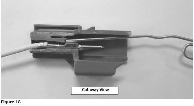
Hint: If using a paper clip or similar to remove the pin, sharpening the tip to a point will help you get the tip under the locking pin easier.
D) Install new pin/wire by gently inserting the pin into the bottom of the connector in the proper orientation (will only slide in properly in one orientation) and sliding it in until it clicks into place and cannot be pulled back out. Replace the locking insert.
7. Install Center High Mount Stop Lamp (CHMSL) Wiring
Wire Harness Installation Notes: The 2010 Mustang has wire harness changes that affect the installation of the Roush Light Bar Wiring Harness. The 10 way connector, in the trunk, which was used as the source of the CHMSL circuit on 05-09 models, is not available.
The CHMSL circuit, on the 2010 Mustang, originates at the Body Control Module (cavity 18) and is a single Yellow/Gray wire to the CHMSL. In order to connect to the CHMSL circuit, the Yellow/Gray wire must be located and the Light Bar Wire Harness spliced to it.
Steps 7. A) through Steps 7. D) are used for Model Years 2005 to 2009 Convertible Mustangs. Steps 7. E) through
Steps 7. G) are used for Model Years 2005 to 2010 Convertible Mustangs.
Steps 7. H) through Steps 7. L) are used for Model Year 2010 Convertible Mustangs.
(05-09 Mustang)
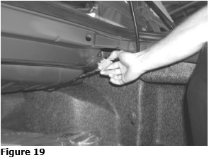
A) Locate the Decklid wiring connector under the trunk ledge on the passenger side of the trunk. Unplug this connector. Refer to Figure 19.
(05-09 Mustang)
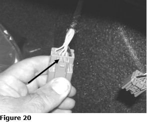
B) Locate the Tan w/ Light Blue Tracer wire in cavity #2 (cavity #s can be found on the back edge of the connector body) of the car side of the connector. Refer to Figure 20. Depin this wire as per the General Wire De-pinning Procedure previous to this section. Pull this wire back an inch or two loose from the rest of the harness removing any harness tape necessary.
(05-09 Mustang)
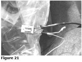
C) Locate the pin on the supplied harness that is furthest from the small black connector that is also on the supplied harness (L11 is printed on the wire). Insert this pin into cavity #2 in place of the pin you just removed. Refer to Figure 21. Cut off the pin from the Tan w/Lt. Blue wire and strip off 3/8” of insulation. Insert stripped portion into the pink crimp connector and crimp the center, metal portion of the connector. Using a Heat Gun or similar tool, Heat the pink crimp connector to shrink and seal the connector.
(05-09 Mustang)
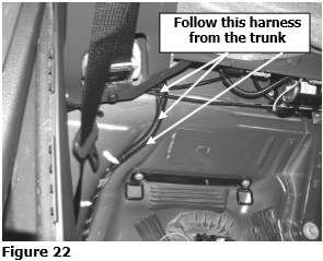
D) Tape the new harness to the existing harness and route the new harness behind the carpeted trim panels and forward, following the factory harness, to the rear seat. Refer to Figure 22.
(05-10 Mustang)
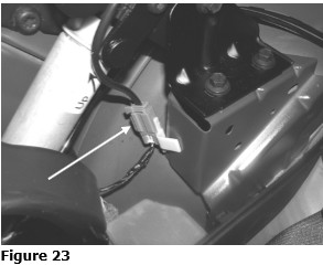
E) Locate the Convertible Top Position Sensor harness in the passenger side quarter panel pocket just rear of the speaker. Refer to Figure 23.
(05-10 Mustang)
F) Unplug this connector and locate the White w/Violet tracer wire (05-09), Yellow w/Gray tracer wire (2010) in cavity #2. De-pin this wire as per the General Wire De-pinning Procedure previous to this section. Refer to Figure 24. Pull this wire back an inch or two loose from the rest of the harness removing any harness tape as necessary.
(05-10 Mustang)
G) Insert the remaining new harness pin (L12B is printed on the wire) into cavity #2. Cut off the pin terminal from the White w/Violet tracer wire (05-09), Yellow w/Gray tracer wire (2010) and strip off 3/8” of the insulation. Insert the stripped portion into the pink crimp connector and crimp the center, metal portion of the connector. Using a Heat Gun or similar tool, Heat the pink crimp connector to shrink and seal the connector. Plug in and reattach the connector. Refer to Figure 25.
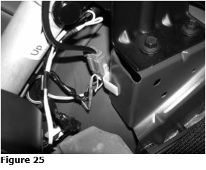
Note: Take special care to insure you are inserting the pin into the same cavity you removed the pin from. There is another empty cavity in the connector.
(2010 Mustang)
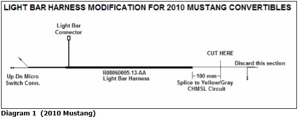
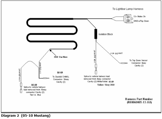
H) Obtain the Light Bar Harness, #R08060005-13-AA, from the Light Bar Kit. Cut the harness per Diagram 1. Strip the insulation 1/2” from the cut end.
(2010 Mustangs)
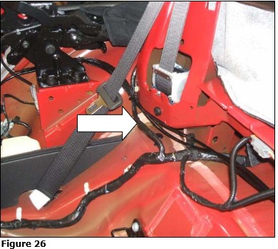
I) Locate the wire harness at the right rear corner of the cabin as shown in Figure 26.
(2010 Mustangs)
J) Remove 5-6 inches of the black loom tape (non-sticky) from the body harness as shown in Figure 27. Locate the Yellow/Gray wire (the only Yellow wire in the bunch).
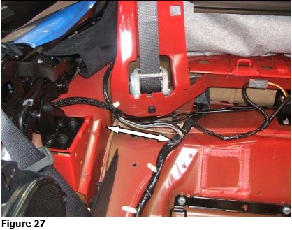
(2010 Mustangs)
K) Using wire strippers remove 3/4” of the wire insulation and splice & solder the cut / stripped end of the Light Bar Wire Harness to the Yellow/Gray wire. Cover the splice with electrical tape.
(2010 Mustangs)
L) Rewrap the wire harness with electrical tape.
8. Installation of ROUSH Light Bar:
A) Feed the LED wire down through the loosely installed passenger side Trim Panel Cap and then through the Light Bar Bracket receiver tube. Evenly lower ROUSH Light Bar partially into holes. Route the LED wire through the speaker bracket and connect it to the small black connector on the newly install light harness. Secure wiring with Zip ties.
B) Install the upper, passenger side portion of the Quarter Trim Panel.
C) Install the passenger side Trim Panel Cap.
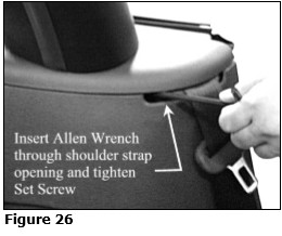
D) Evenly lower the ROUSH Light Bar down to the tops of Trim Panel Caps. With the bottom of the Light Bar flat on the surface of the Trim Panel Caps, tighten the Light Bar Bracket Set Screw. (Refer to Figure 26)
9. Reinstall your back seat:
A) Reinstall by reversing Step 1.
10. Wiring Diagram
Congratulations!!! You have completed the installation of the ROUSH Performance Products, Light Bar Kit. It is recommended that you save all parts removed from your vehicle during the installation of this kit.