FREE 1 to 3-Day Delivery on Orders $119+ Details
Best Sellers


How to Install a Roush 7 Bar Upper Black Billet Grille on Your 2010-2012 Mustang GT
Installation Time
30 minutes
Tools Required
- Philips Screw Driver
- Short Stubby Philips Screw Driver
- Small Slot Screw Driver
- 7 mm wrench
- Ratchet – 1/4" Drive
- 5.5 mm Socket – 1/4" Drive
- 8 mm Socket – 1/4" Drive
- Push Pin Removal Tool - Forked
- Electrical Tape or Wire Ties
Installation
LIMIT OF LIABILITY STATEMENT
The information contained in this publication was accurate and in effect at the time the publication was approved for printing and is subject to change without notice or liability. ROUSH Performance Products (RPP) reserves the right to revise the information presented herein or to discontinue the production of parts described at any time.
SAFETY REQUIREMENTS
STOP! READ IMPORTANT SAFETY CAUTIONS AND WARNINGS BEFORE PROCEEDING.
IMPORTANT SAFETY NOTICE
Appropriate disassembly, assembly methods and procedures are essential to ensure the personal safety of the individual performing the kit installation. Improper installation due to the failure to correctly follow these instructions could cause personal injury or death. Read each step of the installation manual carefully before starting the actual installation.
Therefore, do not allow flames, sparks or flammable substances to come near the battery.
1. Always wear safety glasses for eye protection.
2. Place ignition switch in the OFF position.
3. Always apply the parking brake when working on a vehicle.
4. Chock the front and rear tires to prevent unexpected vehicle movement.
5. If working without a lift, always consult vehicle manual for correct lifting specifications.
6. Operate the engine only in well-ventilated areas to avoid exposure to carbon monoxide.
7. Do not smoke or use flammable items near or around the fuel system.
8. Use chemicals and cleaners in well-ventilated areas.
9. Batteries produce explosive gases, which can cause personal injury.
10. Keeps hands and any other objects away from the radiator fan blades.
11.Keep yourself and your clothing away from moving parts when the engine is running.
12. Do not wear loose clothing or jewelry that can get caught in rotating parts or scratch surface finishes.
13. Allow the engine, cooling system, brakes and exhaust to cool before working on a vehicle.
WORK SAFELY!
Perform this installation on a good clean level surface for maximum safety and with the engine turned off.
Front Fascia Removal
1. Open the vehicle hood and remove eight (8) push pin retainers and the black plastic panel covering the radiator. Refer to Figure 1. Set all parts aside for reinstallation. Note: The push pins are a two (2) part push pin. Remove the center button first to release the barbs and then remove the push pin body.
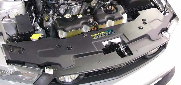
Figure 1
2. Using a 1/4” drive ratchet with a 5.5 mm socket, remove nine (9) screws from the lower close-out panel; one (1) at each wheel well splash shield, four (4) at the front fascia and three (3) at the rear edge of the close-out panel. Refer to Figure 2. Remove the lower close-out panel. Set all parts aside for reinstallation.
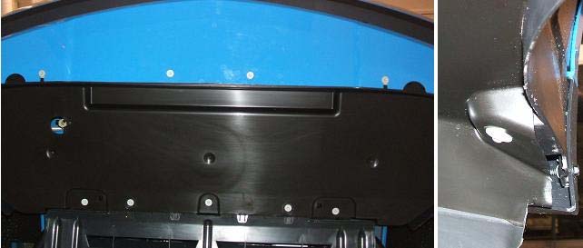
Figure 2
3. Disconnect the left and right side marker lamp connectors. Press the release tab and pull the connector from the side marker lamp. Refer to Figure 3.
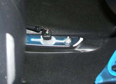
(Left side shown, right side similar.) Figure 3
4. Using a forked push pin tool, remove the ambient temperature sensor from the lower left opening of the front fascia. Refer to Figure 4.
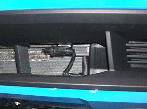
Figure 4
5. Using a 1/4” drive ratchet with an 8 mm socket, remove two (2) screws that attach the top of the fascia to the headlight assemblies. Refer to Figure 5.
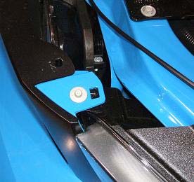
(Left side shown, right side similar.) Figure 5
6. Lift the two (2) upper fascia mounts from the pins on the headlamp assemblies and slightly pull the upper Grille forward to disconnect the left and right fog lamp connectors. Refer to Figure 6. When complete, return the upper fascia mounts to the pins on the head lamp assemblies.
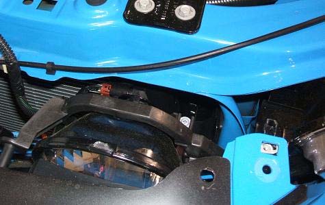
(Left side shown, right side similar.) Figure 6
7. Using a 7 mm wrench, remove two (2) screws from each wheel well opening. Refer to Figure 7.
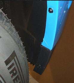
(Right side shown, left side similar.) Figure 7
8. With an assistant, lift the two (2) upper fascia mounts from the pins on the headlamp assemblies and remove the front fascia.
10. Place the fascia assembly onto a cloth covered table to avoid scratching the fascia.
11. Remove the factory Grille surround assembly from the front fascia by releasing four (4) center tabs and three (3) tabs on each end. Refer to Figure 8.
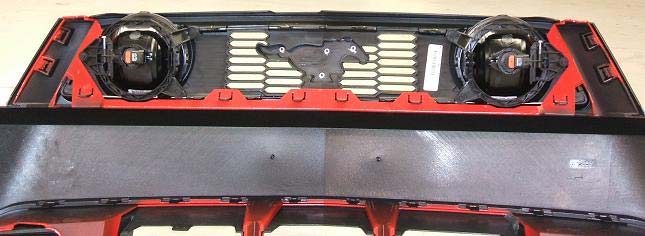
Figure 8
Reinstall the Front Fascia
11. Reinstall the front fascia onto the vehicle. Hook the upper fascia mounts onto the pins of the head light brackets. Reinstall the two (2) bolts, removed in Step 5, to the head light brackets. Refer back to Figure 5. Torque the bolts to 8 Nm (71 lbin).
12. Reinstall two (2) screws, removed in Step 7, to each wheel well (4 total). Refer back to Figure 7.
13. Reconnect the left and right side marker connectors. Refer back to Step 3, Figure 3. Ensure the connectors are fully inserted and snap into place.
14. Reinstall the Ambient Temperature Sensor. Refer back to Step 4, Figure 4.
15. Reinstall the lower close-out panel using the nine (9) screws removed in Step 2. Refer back to Figure 2.
Replacing the Grille
16. Remove six (6) screws (3 per side) and the two (2) fog lamp assemblies from the factory Grille assembly. Refer to Figure 9.
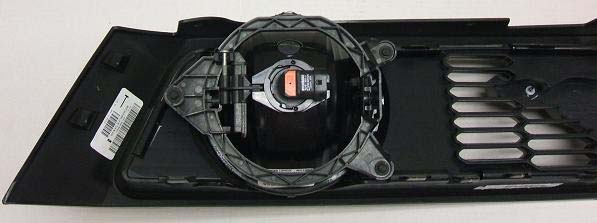
Figure 9
17. Remove the Grille from the Grille surround.
- In the upper part of each fog lamp opening, unhook the Grille from the surround as shown in Figure 10.
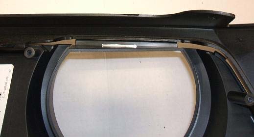
Figure 10
- At the same time, unhook the two end tabs. Refer to Figure 11
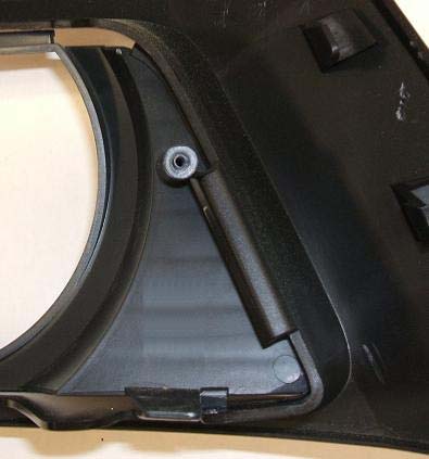
Figure 11
- Next, using a small screw driver, release the eight retainer tabs to separate the Grille from the surround. Refer to Figure 12.
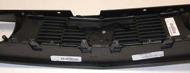
Figure 12
Assemble and Install the Billet Grille
18. Install the eight (8) Clip Nuts to the Brackets as shown in Figure 13.
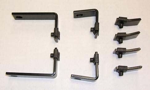
Figure 13
19. Install the two (2) Short L Brackets to the upper mounting holes as shown in Figure 14. Do not tighten the screws at this time.
20. Install the two (2) Long L Brackets to the lower mounting holes as shown in Figure 14. Do not tighten the screws at this time.
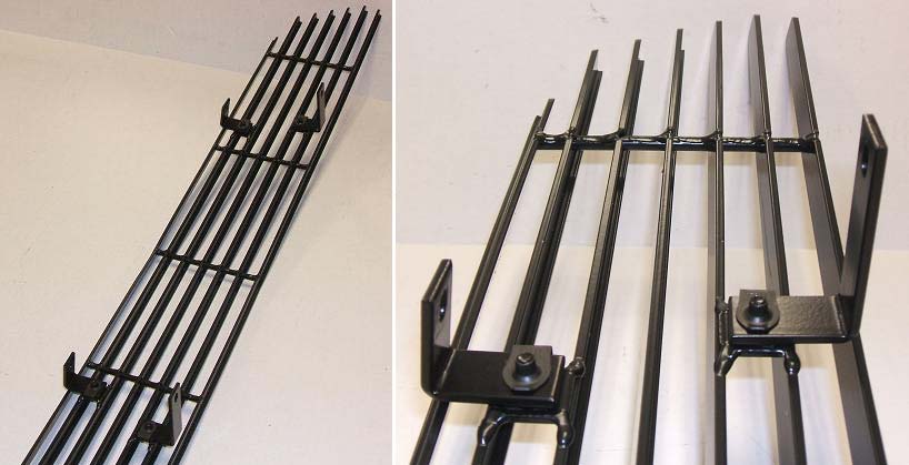
Figure 14
21. Insert the four Bracket ends into the four (4) slots on the Grille surround as shown in Figure 15. (Right side shown, left side is similar)
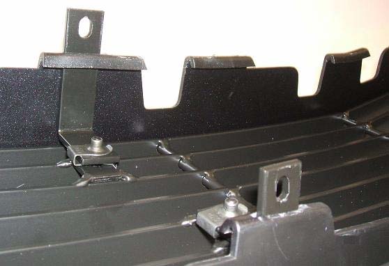
Figure 15
22. Loosely install the four (4) Pinch Brackets to the L Brackets as shown in Figure 16.
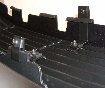
Figure 16
23. Align the Grille in the surround opening with equal distance at the left and right ends. Push the upper mount full forward and tighten the top two (2) upper Pinch Bracket screws. Align the lower corners as shown and tighten the bottom two (2) lower Pinch Bracket screws. Refer to Figure 17.
(Upper) (Lower)
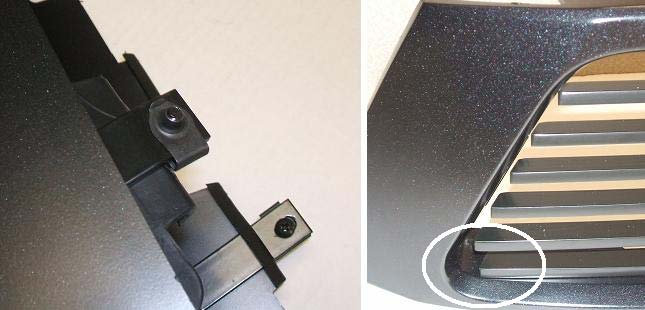
Figure 17
24. Loosen and retighten the four (4) L Bracket screws. Refer to Figure 18.
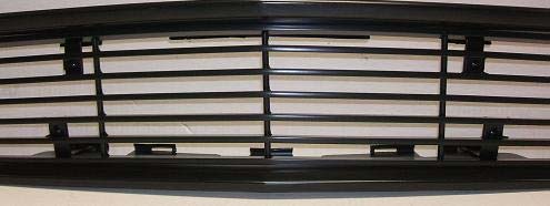
Figure 18
25. Using electrical tape or wire ties, secure the fog lamp wires and connectors. Refer to Figure 19.
RH Side LH Side
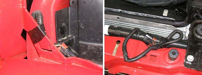
Figure 19
26. Align the two (2) end tabs on each end of the Grille assembly to the end slots on the front fascia. Note: The six lower tabs were on the Grille and are not used. Press the Grille assembly into place. Refer back to Figure 8. Ensure all four (4) end retainer tabs are fully inserted into there respective slots.
27. Install the Grille Lower Retainer Bracket with the bent tabs up. Press on the two (2) Press Clips as shown. Refer to Figure 20. Ensure the bracket is hooked onto the center lower tab on the Grille surround.
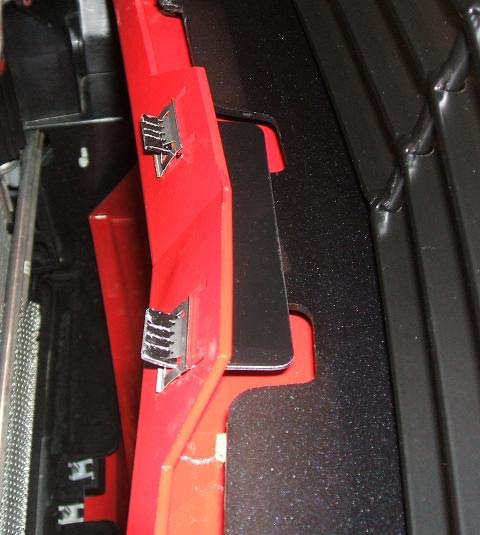
Figure 20
28. Reinstall the upper radiator cover and eight (8) push pins removed in Step 1. Refer back to Figure 1. Insert the push pin body into the hole and then the push pin button.
29. Close the hood.
Congratulations!!! You have completed the installation of the ROUSH Performance Products, Upper Billet Grille Kit. It is recommended that you save all parts removed from your vehicle during the installation of this kit.